
This menu is not available on the FL MGUARD BLADE controller.
|
This menu is not available on the FL MGUARD BLADE controller. |
|
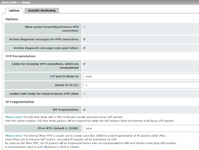
IPsec VPN >> Global >> Options |
||
|---|---|---|
|
Allow packet forwarding between VPN connections |


|
|
|
|
|
When the function is deactivated (default): VPN connections exist separately. There is no packet forwarding between the configured VPN connections. When the function is activated: “hub and spoke” feature enabled: acting as a control center, the mGuard diverts VPN connections to several branches that can then also communicate with each other. 
|
|
|
|
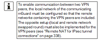
With a star VPN connection topology, mGuard peers can also exchange data with one another. In this case, it is recommended that the local mGuard consults CA certificates for the authentication of peers (see "Authentication" on page 342). |
|
|
|
In the case of “hub and spoke”, 1:1 NAT of the peer is not supported. |
|
|
Function deactivated (default) If errors occur when establishing VPN connections, the mGuard logging function can be used to find the source of the error based on corresponding entries (see Logging >> Browse Local Logs menu item). This option for error diagnostics is used as standard. If it is sufficient, you can deactivate the function at this point. Function activated If the option of diagnosing VPN connection problems using the mGuard logging function is too impractical or insufficient, select this option. This may be the case if the following conditions apply: –In certain application environments, e.g., when the mGuard is “operated” by means of a machine controller via the CMD contact (only for FL MGUARD RS4000/RS2000, TC MGUARD RS4000/RS2000 3G, TC MGUARD RS4000/RS2000 4G, FL MGUARD RS4004/RS2005, and FL MGUARD RS, FL MGUARD GT/GT), the option for a user to view the mGuard log file via the web-based user interface of the mGuard may not be available at all. –When used remotely, it is possible that a VPN connection error can only be diagnosed after the mGuard is temporarily disconnected from its power source – which causes all the log entries to be deleted. |
|
|
|
|
–The relevant log entries of the mGuard that could be useful may be deleted because the mGuard regularly deletes older log entries on account of its limited memory capacity. –If an mGuard is being used as the central VPN peer, e.g., in a remote maintenance center as the gateway for the VPN connections of numerous machines, the messages regarding activity on the various VPN connections are logged in the same data stream. The resulting logging volume makes it time-consuming to find the information relevant to one error. |
|
|
|
After archiving is enabled, relevant log entries about the operations involved in establishing VPN connections are archived in the non-volatile memory of the mGuard if the connections are established as follows: –Via the CMD contact –Via text message –Via the “Start” icon on the web interface –Via the CGI interface nph-vpn.cgi using the “synup” command (see application note: “How to use the CGI Interface”). (Application notes are available in the download area of phoenixcontact.net/products.) –Archived log entries are not affected by a restart. They can be downloaded as part of the support snapshot (Hardware menu item). A snapshot provides your supplier's support team with additional options for more efficient troubleshooting than would be possible without archiving. |
|
|
Archive diagnostic messages only upon failure (Only when Archiving is activated) |
If only log entries generated for failed connection attempts are to be archived, activate the function. When the function is deactivated, all log entries will be archived. |
This function is used to encapsulate data packets to be transmitted via a VPN connection in TCP packets. Without this encapsulation, under certain circumstances it is possible for VPN connections that important data packets belonging to the VPN connection may not be correctly transmitted due to interconnected NAT routers, firewalls or proxy servers, for example.
Firewalls, for example, may be set up to prevent any data packets of the UDP protocol from passing through or (incorrectly implemented) NAT routers may not manage the port numbers correctly for UDP packets.
TCP encapsulation avoids these problems because the packets belonging to the relevant VPN connection are encapsulated in TCP packets, i.e., they are hidden so that only TCP packets appear for the network infrastructure.
The mGuard may receive VPN connections encapsulated in TCP, even when it is positioned behind a NAT gateway in the network and thus cannot be reached by the VPN peer under its primary external IP address. To do this, the NAT gateway must forward the corresponding TCP port to the mGuard (see "Listen for incoming VPN connections, which are encapsulated" on page 317).
|
TCP encapsulation can only be used if an mGuard (Version 6.1 or later) is used at both ends of the VPN tunnel. The "Path Finder" function can be used from version 8.3 and also functions with the mGuard Secure VPN Client. |
|
TCP encapsulation should only be used if required, because connections are slowed down by the significant increase in the data packet overhead and by the correspondingly longer processing times. |
|
If the mGuard is configured to use a proxy for HTTP and HTTPS in the Network >> Proxy Settings menu item, then this proxy is also used for VPN connections that use TCP encapsulation. |
|
TCP encapsulation supports the basic authentication and NTLM authentication methods for the proxy. The "Path Finder" function also supports the "Digest" authentication process. |
|
For the TCP encapsulation to work through an HTTP proxy, the proxy must be named explicitly in the proxy settings (Network >> Proxy Settings menu item) (i.e., it must not be a transparent proxy) and this proxy must also understand and permit the HTTP method CONNECT. |
|
To use the “Path Finder” function to establish a VPN connection to an mGuard Secure VPN Client, the function must be enabled on both sides of the connection (server and client). |
|
TCP encapsulation does not work in conjunction with authentication via pre-shared key (PSK). |
|
TCP encapsulation only works if one of the two ends is waiting for connections (connection initiation: wait) and is given as address of the "%any" peer VPN gateway. |
TCP encapsulation with enabled “Path Finder” function
TCP encapsulation with enabled “Path Finder” function improves the behavior of the standard TCP encapsulation described above.
When the connection has been newly set up and no reverse compatibility is required, the Path Finder function should be used.
If a VPN connection is started by the mGuard Secure VPN Client, which is positioned behind a proxy server or a firewall, the “Path Finder” function must be enabled in the mGuard Secure VPN Client as well as in the mGuard (server). The data packets to be transmitted via the VPN connection are encapsulated in TCP packets (see "TCP encapsulation" on page 315).

Figure 10-1: TCP encapsulation in an application scenario with a maintenance center and machines maintained remotely via VPN connections
|
TCP encapsulation |
Listen for incoming VPN connections, which are encapsulated |
Default setting: deactivated Only activate this function if the TCP encapsulation function is used. Only then can the mGuard allow connection establishment with encapsulated packets. 
The interfaces to be used for listening are determined by the mGuard according to the settings on the active VPN connections that have “%any” configured as the peer. The decisive setting is specified under “Interface to use for gateway setting %any”. |
|
|
TCP port to listen on (For TCP encapsulation) |
Default: 8080 Number of the TCP port where the encapsulated data packets to be received arrive. The port number specified here must be the same as the one specified for the mGuard of the peer as the TCP port of the server, which accepts the encapsulated connection (IPsec VPN >> Connections menu item, Edit, General tab page). The following restriction applies: The port to be used for listening must not be identical to: –A port that is being used for remote access (SSH, HTTPS or SEC-Stick) –The port which is used for listening with enabled Path Finder function |
|
|
Server ID (0-63) (For TCP encapsulation) |
The default value 0 does not usually have to be changed. The numbers are used to differentiate between different control centers. A different number is only to be used in the following scenario: an mGuard connected upstream of a machine must establish connections to two or more different maintenance centers and their mGuard devices with TCP encapsulation enabled. |
|
|
Enable Path Finder for mGuard Secure VPN Client |
Default setting: deactivated Only activate this function if the mGuard should accept a VPN connection from an mGuard Secure VPN Client that is positioned behind a proxy server or a firewall. The “Path Finder” function must also be enabled in the mGuard Secure VPN Client. |
|
|
TCP port to listen on (For Path Finder) |
Default: 443 Number of the TCP port where the encapsulated data packets to be received arrive. The port number specified here must be the same as the one specified for the VPN client of the peer as the TCP port of the server, which accepts the encapsulated connection. The mGuard Secure VPN Client always uses port 443 as the destination port. It is when the port is overwritten by a firewall between the mGuard Secure VPN Client and the mGuard that the port in the mGuard has to be changed. The following restriction applies: The port to be used for listening must not be identical to: –A port that is being used for remote access (SSH, HTTPS or SEC-Stick) –The port which is used for listening with enabled TCP encapsulation function |
|
IP Fragmentation |
IKE fragmentation |
UDP packets can be oversized if an IPsec connection is established between the participating devices via IKE and certificates are exchanged. Some routers are not capable of forwarding large UDP packets if they are fragmented over the transmission path (e.g., via DSL in 1500-byte segments). Some faulty devices forward the first fragment only, resulting in connection failure. If two mGuard devices communicate with each other, it is possible to ensure at the outset that only small UDP packets are to be transmitted. This prevents packets from being fragmented during transmission, which can result in incorrect routing by some routers. If you want to use this option, activate the function. 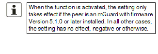
|
|
|
IPsec MTU (default is 16260) |
The option for avoiding oversized IKE data packets, which cannot be routed correctly on the transmission path by faulty routers, can also be applied for IPsec data packets. In order to remain below the upper limit of 1500 bytes often set by DSL, it is recommended that a value of 1414 (bytes) be set. This also allows enough space for additional headers. If you want to use this option, specify a value lower than the default setting. |

For an explanation of DynDNS, see "DynDNS" on page 212.
|
Watch hostnames of remote VPN gateways |
If the mGuard has the address of a VPN peer in the form of a host name (see "Defining a new VPN connection/VPN connection tunnel" on page 322) and this host name is registered with a DynDNS service, then the mGuard can check the relevant DynDNS at regular intervals to determine whether any changes have occurred. If so, the VPN connection will be established to the new IP address. |
|
|
|
Default: 300 seconds |
|
Requirements for a VPN connection
A general requirement for a VPN connection is that the IP addresses of the VPN partners are known and can be accessed.
–mGuard devices provided in stealth network mode are preset to the “multiple clients” stealth configuration. In this mode, you need to configure a management IP address and default gateway if you want to use VPN connections (see "Default gateway" on page 150). Alternatively, you can select a different stealth configuration than the “multiple clients” configuration or use another network mode.
–In order to successfully establish an IPsec connection, the VPN peer must support IPsec with the following configuration:
–Authentication via pre-shared key (PSK) or X.509 certificates
–ESP
–Diffie-Hellman group (2, 5 and 14 – 18)
–DES, 3DES or AES encryption
–MD5- and SHA hash algorithms
–Tunnel or transport mode
–XAuth and Mode Config
–Quick mode
–Main mode
–SA lifetime (1 second to 24 hours)
If the peer is a computer running Windows 2000, the Microsoft Windows 2000 High Encryption Pack or at least Service Pack 2 must be installed.
–If the peer is positioned downstream of a NAT router, the peer must support NAT traversal (NAT-T). Alternatively, the NAT router must know the IPsec protocol (IPsec/VPN passthrough). For technical reasons, only IPsec tunnel connections are supported in both cases.
–Authentication using “Pre-shared key” in Aggressive mode is not supported when using “XAuth”/“Mode Config”. If, e.g., a connection from the iOS or Android client to the mGuard server is created, the authentication must take place via certificate.
Encryption and hash algorithms
Some of the available algorithms are obsolete and are no longer considered secure. This is why they are not to be recommended. For reasons of reverse compatibility however they can still be selected and used in the mGuard.
|
NOTE: Use secure encryption and hash algorithms (see "Using secure encryption and hash algorithms" on page 21). |

Lists all the VPN connections that have been defined.
Each connection name listed here can refer to an individual VPN connection or a group of VPN connection tunnels. You have the option of defining several tunnels under the transport and/or tunnel settings of the relevant entry.
You also have the option of defining new VPN connections, activating and deactivating VPN connections, changing (editing) the VPN connection or connection group properties, and deleting connections.
|
License Status |
VPN license counter |
Number of peers that currently have a VPN connection established using the IPsec protocol. |
|
|
OpenVPN license counter |
Number of peers to which a VPN connection is currently established using the OpenVPN protocol. |
|
Connections |
Initial mode |
Disabled / Stopped / Started The “Disabled” setting deactivates the VPN connection permanently; it cannot be started or stopped. The “Started” and “Stopped” settings determine the state of the VPN connection after restarting/booting the mGuard (e.g., after an interruption in the power supply). VPN connections that are not deactivated can be started or stopped via icons on the web interface, via text message, a switch, a pushbutton, data traffic or the script nph-vpn.cgi. |
|
|
State |
Indicates the current activation state of the IPsec VPN connection. |
|
|
ISAKMP SA |
Indicates whether or not the corresponding ISAKMP SA has been established. |
|
|
IPsec SA |
Indicates how many of the configured tunnels are established. The number of established tunnels may be higher than the number of configured tunnels, if the “Tunnel Group” function is used. |
|
|
Name |
Name of the VPN connection |
Connections
Defining a new VPN connection/VPN connection tunnel
•In the connection table, click on the  Insert Row icon to add a new table row.
•Click on the  Edit Row icon.
Editing a VPN connection/VPN connection tunnel
•Click on the  Edit Row icon in the relevant row.
URL for starting, stopping, querying the status of a VPN connection
The following URL can be used to start and stop VPN connections that are in “Started” or “Stopped” initial mode or to query their connection status:
Example (only mGuard firmware Version < 8.4.0)
https://server/nph-vpn.cgi?name=verbindung&cmd=(up|down|status)
wget --no-check-certificate "https://admin:mGuard@192.168.1.1/nph-vpn.cgi?name=Athen&cmd=up"
|
Using the command line tool wget only functions in combination with mGuard firmware versions < 8.4.0. From mGuard firmware Version 8.4.0, the command line tool curl can be used (parameters and options differ!). Example: curl --insecure "https://admin:mGuard@192.168.1.1/nph-vpn.cgi?name=Athen&cmd=up" |
|
The admin password and the name that an action relates to may only contain the following characters: –Letters: A - Z, a - z –Numbers: 0 - 9 –Characters: - . _ ~ Other characters, such as a space or question mark, must be encoded accordingly (see "Encoding of special characters (URL encoding)" on page 453). |
The option --no-check-certificate (wget) or --insecure (curl) ensures that the HTTPS certificate on the mGuard does not undergo any further checking.
A command like this relates to all connection tunnels that are grouped together under the respective name (in this example, Athen). This is the name that is listed under IPsec VPN >> Connections >> Edit >> General as "A descriptive name for the connection" . In the event of ambiguity, the URL call only affects the first entry in the list of connections.
It is not possible to communicate with the individual tunnels of a VPN connection. If individual tunnels are deactivated, they are not started. Starting and stopping in this way therefore has no effect on the settings of the individual tunnels (see "Transport and Tunnel Settings" on page 332).
If the status of a VPN connection is queried using the URL specified above, then the following responses can be expected:
|
Indicates |
|
|---|---|
|
unknown |
A VPN connection with this name does not exist. |
|
void |
The connection is inactive due to an error, e.g., the external network is down or the host name of the peer could not be resolved in an IP address (DNS). The response “void” is also issued by the CGI interface, even if no error occurred. If, for example, the VPN connection is deactivated according to the configuration (No set in column) and has not been enabled temporarily using the CGI interface or CMD contact. |
|
ready |
The connection is ready to establish tunnels or allow incoming queries regarding tunnel setup. |
|
active |
At least one tunnel has already been established for the connection. |
Defining a VPN connection/VPN connection tunnel
Depending on the network mode of the mGuard, the following page appears after clicking on the  Edit Row icon.

|
Options |
The connection can be freely named/renamed. If several connection tunnels are defined under , then this name applies to the entire set of VPN connection tunnels grouped under this name. Similarities between VPN connection tunnels: –Same authentication method, as specified on the Authentication tab page (see "Authentication" on page 342) –Same firewall settings –Same IKE options set |
|
|
|
Initial mode |
Disabled / Stopped / Started The “Disabled” setting deactivates the VPN connection permanently; it cannot be started or stopped. The “Started” and “Stopped” settings determine the status of the VPN connection after restarting/booting the mGuard (e.g., after an interruption in the power supply). VPN connections that are not deactivated can be started or stopped via icons on the web interface, via text message, a switch, a pushbutton, data traffic or the script nph-vpn.cgi. |
|
|
An IP address, host name or %any for several peers or peers downstream of a NAT router. |
|
Address of the remote site's VPN gateway

Figure 10-2: The address of the transition to the private network where the remote communication partner is located.
–If the mGuard should actively initiate and establish the connection to the remote peer, specify the IP address or host name of the peer here.
–If the VPN gateway of the peer does not have a fixed and known IP address, the DynDNS service (see glossary) can be used to simulate a fixed and known address.
–If the mGuard should be ready to allow a connection to the local mGuard that was actively initiated and established by a remote peer with any IP address, specify %any.
This setting should also be selected for a VPN star configuration if the mGuard is connected to the control center.
The mGuard can then be “called” by a remote peer if this peer has been dynamically assigned its IP address (by the Internet service provider), i.e., it has an IP address that changes. In this scenario, you may only specify an IP address if the remote “calling” peer also has a fixed and known IP address.
|
%any can only be used together with the authentication method using X.509 certificates. |
|
If locally stored CA certificates are to be used to authenticate the peer, the address of the remote site's VPN gateway can be specified explicitly (by means of an IP address or host name) or by %any. If it is specified using an explicit address (and not by “%any”), then a VPN identifier (see "VPN Identifier" on page 345) must be specified. |
|
%any must be selected if the peer is located downstream of a NAT gateway. Otherwise, the renegotiation of new connection keys will fail on initial contact. |
|
If TCP encapsulation is used (see "TCP encapsulation" on page 315): a fixed IP address or a host name must be specified if this mGuard is to initiate the VPN connection and encapsulate the VPN data traffic. If this mGuard is installed upstream of a maintenance center to which multiple remote mGuard devices establish VPN connections and transmit encapsulated data packets, %any must be specified for the VPN gateway of the peer. |
.
|
Options |
Address of the remote site's VPN gateway |
IP address, host name or “%any” for any IP addresses, several peers or peers downstream of a NAT router. |
|
|
Interface to use for gateway setting %any (If %any was specified for “Address of the remote site's VPN gateway”) |
Internal, External, External 2, Dial-in, DMZ, Implicitly chosen by the IP address specified to the right External 2 and Dial-in are only for devices with a serial interface, see "Network >> Interfaces" on page 131. Selection of the Internal option is not permitted in Stealth mode. This interface setting is only considered when “%any” is entered as the address of the remote site's VPN gateway. In this case, the interface of the mGuard through which it answers and permits requests for the establishment of this VPN connection is set here. The VPN connection can be established through the LAN and WAN port in all Stealth modes when External is selected. The interface setting allows encrypted communication to take place over a specific interface for VPN peers without a known IP address. If an IP address or host name is entered for the peer, then this is used for the implicit assignment to an interface. The mGuard can be used as a “single-leg router” in Router mode when Internal is selected, as both encrypted and decrypted VPN traffic for this VPN connection is transferred over the internal interface. IKE and IPsec data traffic is only possible through the primary IP address of the individual assigned interface. This also applies to VPN connections with a specific peer. |
|
|
|
DMZ can only be selected in Router mode. Here, VPN connections can be established to hosts in the DMZ and IP packets can be routed from the DMZ in a VPN connection. Implicitly chosen by the IP address below: an IP address is used instead of a dedicated interface. |
|
|
IP address to use for gateway setting %any |
IP address that is used for gateway setting %any. |
|
|
Initiate / Initiate on traffic / Wait Initiate The mGuard initiates the connection to the peer. The fixed IP address of the peer or its name must be entered in the Address of the remote site's VPN gateway field (see above). Initiate on traffic The connection is initiated automatically when the mGuard sees that the connection should be used. (Can be selected for all operating modes of the mGuard (Stealth, Router, etc.)) 
Wait The mGuard is ready to allow the connection to the mGuard that a remote peer actively initiates and establishes. 
|
|
|
|
(Only available with the TC MGUARD RS4000/RS2000 3G, TC MGUARD RS4000/RS2000 4G, FL MGUARD RS4000/RS2000, FL MGUARD GT/GT, FL MGUARD RS4004/RS2005 and FL MGUARD RS.) |
None / Service input CMD 1-3 The VPN connection can be switched via a connected pushbutton/switch. The pushbutton/switch must be connected to one of the service contacts (CMD 1-3). 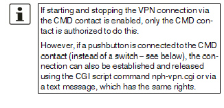

|
|
|
Use inverted control logic |
Inverts the behavior of the connected switch. If the switching service input is configured as an on/off switch, it can activate one VPN connection while simultaneously deactivating another which uses inverted logic, for example. |
|
|
Deactivation timeout |
Time, after which the VPN connection is stopped, if it has been started via a text message, switch, pushbutton, nph-vpn.cgi or the web interface. The timeout starts on transition to the “Started” state. After the timeout has elapsed, the connection remains in the “Stopped” state until it is restarted. Exception: “Initiate on traffic” A connection initiated (established) by data traffic is released after the timeout has elapsed, but remains in the “Started” state. The timeout only starts once there is no more data traffic. The VPN connection is established again when data traffic resumes. Time in hours, minutes and/or seconds (00:00:00 to 720:00:00, around 1 month). The entry can be in seconds [ss], minutes and seconds [mm:ss] or hours, minutes, and seconds [hh:mm:ss]. 0 means the setting is disabled. |
|
|
Token for text message trigger (Only available with the TC MGUARD RS4000/RS2000 3G, TC MGUARD RS4000/RS2000 4G.) |
Incoming text messages can be used to start or stop VPN connections. The text message must contain the “vpn/start” or “vpn/stop” command followed by the token. |
|
|
Encapsulate the VPN traffic in TCP |
No / TCP encapsulation / Path Finder (default: No) If the TCP encapsulation function is used (see "TCP encapsulation" on page 315), only set this option to TCP encapsulation if the mGuard is to encapsulate its own outgoing data traffic for the VPN connection it initiated. In this case, the number of the port where the peer receives the encapsulated data packets must also be specified. TPC encapsulation can also be used with the “Path Finder” function (see "TCP encapsulation with enabled “Path Finder” function" on page 316). In this case, only set this option to Path Finder if the peer also supports the “Path Finder” function. The number of the port where the peer receives the encapsulated data packets must then also be specified. For TCP encapsulation / Path Finder the mGuard does not attempt to create the VPN connection via the standard IKE encryption (UDP-Port 500 and 4500), but always sends it via TCP protocol. Connection startup setting when using TCP encapsulation/Path Finder –If the mGuard is to establish a VPN connection to a maintenance center and encapsulate the data traffic there: –“Initiate” or “Initiate on traffic” must be specified. –If the mGuard is installed at a maintenance center to which mGuard devices establish a VPN connection: –“Wait” must be specified. |
|
|
TCP-Port of the server, which accepts the encapsulated connection (Only visible if “Encapsulate the VPN traffic in TCP” is set to TCP encapsulation or Path Finder.) |
Default: 8080 Number of the port where the encapsulated data packets are received by the peer. The port number specified here must be the same as the one specified for the mGuard of the peer under TCP port to listen on (IPsec VPN >> Global >> Options menu item). |
|
The mGuard supports the "Extended Authentication" authentication method (XAuth) and the frequently required "Mode Config" protocol extension including "Split Tunneling“ as the server and as the client (including iOS and Android-support). Network settings and DNS and WINS configurations are communicated to the IPsec client by the IPsec server. |
||
|
|
Mode configuration |
Off / Server / Client (default: Off) In order to communicate via an IPsec VPN connection as the server or client with peers that require “XAuth” and “Mode Config”, select “Server” or “Client”. Off: do not use “Mode Config”. Server: communicate the IPsec network configuration to the peer. Client: accept and apply the IPsec network configuration communicated by the peer. 
|
|
|
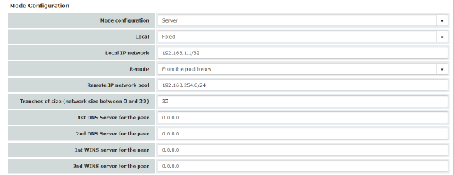
Settings as server Allows clients that require “XAuth” and “Mode Config” (e.g., Apple iPad) to establish an IPsec VPN connection to the mGuard. The remote clients receive the necessary values for configuring the connection (local and remote network) from the mGuard. 
|
|
|
||
|
|
Local |
Fixed / From table below Fixed: the local network on the server side is manually set and fixed and must also be set manually on the client side (on the remote client). From table below: the local network(s) on the server side is/are communicated to the remote client using the split tunneling extension. Entry in CIDR format (see "CIDR (Classless Inter-Domain Routing)" on page 29). |
|
|
Local IP network (If “Fixed” was selected) |
Local network at the server end in CIDR format. |
|
|
Networks (If “From table below” was selected) |
Local network at the server end in CIDR format. |
|
|
Remote |
From pool below / From table below From pool below The server dynamically selects IP networks for the peer from the specified pool according to the selected tranche size. From table below (This function can only be used if an mGuard is used at the peer.) The IP networks of the peer are communicated to the remote client using the split tunneling extension. |
|
|
Remote IP network pool (If “From pool” was selected) |
Network pool from which IP networks for the peer are selected, in CIDR format. |
|
|
Tranches of size (network size between 0 and 32) (If “From pool” was selected) |
Section sizes which determine the size of the IP networks which can be taken from the network pool for the peer. |
|
|
Networks (If “From table below” was selected) |
IP networks for the peer in CIDR format. |
|
|
1st and 2nd DNS server for the peer |
Address of a DNS server which is communicated to the peer. The setting 0.0.0.0 means “no address”. |
|
|
1st and 2nd WINS server for the peer |
Address of a WINS server which is communicated to the peer. The setting 0.0.0.0 means “no address”. |
|
|
Settings as client Allows the mGuard to establish an IPsec VPN connection to servers that require “XAuth” and “Mode Config”. As an option, the mGuard receives the necessary values (IP address/IP network) for configuring the connection (local and remote network) from the remote server of the peer. |
|

|
||
|
|
Local NAT (Not active in Stealth modes “Autodetect” and “Static”)
|
No NAT / Masquerade No NAT Local IP addresses selected by the server can use the tunnel. Masquerade The mGuard can masquerade its local network. To do this, the local network must be specified in CIDR format (see "CIDR (Classless Inter-Domain Routing)" on page 29). |
|
|
Local IP network |
IP network at the local interface of the client that is masqueraded. |
|
|
Remote |
Fixed / From Server Fixed: the local network on the client side is manually set and fixed and must also be set manually on the server side (on the remote server). From Server: the remote network(s) on the server side is/are communicated to the local client using the split tunneling extension. If the remote server does not use split tunneling, 0.0.0.0/0 is used. |
|
|
Remote IP network (If “Fixed” was selected) |
The network of the remote server in CIDR format. |
|
|
XAuth login |
Some remote servers require an XAuth user name (login) and an XAuth password in order to authenticate the client. |
|
|
XAuth password |
Corresponding XAuth password |
|
|
||

|
||
|
|
Enabled |
Specify whether the connection tunnel should be active or not. |
|
|
Comment |
Freely selectable comment text. Can be left empty. |
|
|
Type |
The following can be selected: –Tunnel (network ↔ network) –Transport (host ↔ host) Tunnel (network ↔ network) This connection type is suitable in all cases and is also the most secure. In this mode, the IP datagrams to be transmitted are completely encrypted and are, with a new header, transmitted to the VPN gateway of the peer – the “tunnel end”. The transmitted datagrams are then decrypted and the original datagrams are restored. These are then forwarded to the destination computer. 
Transport (host ↔ host) For this type of connection, only the data of the IP packets is encrypted. The IP header information remains unencrypted. When you switch to Transport, the following fields (apart from Protocol) are hidden as these parameters are omitted. |
|
|
Local (For “Tunnel” connection type) |
Define the network areas for both tunnel ends under Local and Remote. Local: here, specify the address of the network or computer which is connected locally to the mGuard. |
|
|
(For “Tunnel” (network ↔ network) connection type) |
Remote: here, specify the address of the network or computer which is located downstream of the remote VPN gateway. |
|
|
Local NAT (For “Tunnel” connection type) |
No NAT / 1:1 NAT / Masquerade It is possible to translate the IP addresses of devices located at the respective end of the VPN tunnel. No NAT: NAT is not performed. With 1:1 NAT, the IP addresses of devices at the local end of the tunnel are exchanged so that each individual address is translated into another specific address. 
With Masquerade, the IP addresses of devices at the local end of the tunnel are exchanged with an IP address that is identical for all devices. |
|
|
Remote NAT (For “Tunnel” connection type) |
No NAT / 1:1 NAT / Masquerade No NAT: NAT is not performed. With 1:1 NAT, the IP addresses of devices of the tunnel peer are exchanged so that each individual address is translated into another specific address. With Masquerade, the IP addresses of devices of the peer are exchanged with an IP address that is identical for all devices. |
|
|

|
|
|
|
Click on the |
|
|
||
|
Transport and Tunnel Settings (Edit) |
||
|
Options |
Enabled |
Specify whether the connection tunnel should be active or not. |
|
|
Comment |
Freely selectable comment text. Can be left empty. |
|
|
Type |
The following can be selected: –Tunnel (network ↔ network) –Transport (host ↔ host) Tunnel (network ↔ network) This connection type is suitable in all cases and is also the most secure. In this mode, the IP datagrams to be transmitted are completely encrypted and are, with a new header, transmitted to the VPN gateway of the peer – the “tunnel end”. The transmitted datagrams are then decrypted and the original datagrams are restored. These are then forwarded to the destination computer. 
Transport (host ↔ host) For this type of connection, only the data of the IP packets is encrypted. The IP header information remains unencrypted. When you switch to Transport, the following fields (apart from Protocol) are hidden as these parameters are omitted. |
|
|
Local (For “Tunnel” connection type) |
Define the network areas for both tunnel ends under Local and Remote. Local: here, specify the address of the network or computer which is connected locally to the mGuard. |
|
|
(For “Tunnel” connection type) |
Remote: here, specify the address of the network or computer which is located downstream of the remote VPN gateway. |
|
Local NAT |
Local NAT for IPsec tunnel connections (For “Tunnel” connection type) |
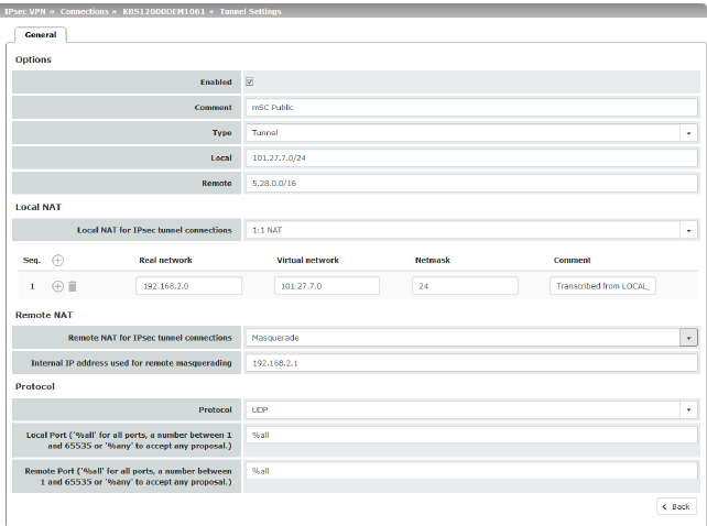
No NAT / 1:1 NAT / Masquerade It is possible to translate the IP addresses of devices located at the respective end of the VPN tunnel. No NAT: NAT is not performed. With 1:1 NAT, the IP addresses of devices at the local end of the tunnel are exchanged so that each individual address is translated into another specific address. With Masquerade, the IP addresses of devices at the local end of the tunnel are exchanged with an IP address that is identical for all devices. |
|
|
|
If local devices transmit data packets, only those data packets are considered which: –Are actually encrypted by the mGuard (the mGuard only forwards packets via the VPN tunnel if they originate from a trustworthy source). –Originate from a source address within the network which is defined here. –Have their destination address in the Remote network if 1:1 NAT is not set there for the peer. The data packets of local devices are assigned a source address according to the address set under Local and are transmitted via the VPN tunnel. |
|
|
|
You can specify 1:1 NAT rules for each VPN tunnel for local devices. In this way, an IP area that is distributed over a wide network can be gathered and sent through a narrow tunnel. |
|
|
|
|

|
||
|
|
Real network |
Configures the “From IP” address for 1:1 NAT. |
|
|
Virtual network |
Configures the translated IP address for 1:1 NAT. |
|
|
Netmask |
The netmask as a value between 1 and 32 for the real and virtual network address (see also "CIDR (Classless Inter-Domain Routing)" on page 29). |
|
|
Comment |
Can be filled with appropriate comments. |
|
|
Internal network address for local masquerading (When “Masquerade” is selected) |
If local devices transmit data packets, only those data packets are considered which: –Are actually encrypted by the mGuard (the mGuard only forwards packets via the VPN tunnel if they originate from a trustworthy source). –Originate from a source address within the network which is defined here. –Have their destination address in the Remote network if 1:1 NAT is not set for the Remote NAT. |
|
|
|
Only one IP address (subnet mask /32) is permitted as the VPN network for this setting. The network to be masqueraded is translated to this IP address. The data packets are then transmitted via the VPN tunnel. Masquerading changes the source address (and source port). The original addresses are recorded in an entry in the Conntrack table. Where response packets are received via the VPN tunnel and there is a matching entry in the Conntrack table, these packets have their destination address (and destination port) written back to them. |
|
Remote NAT |
Remote NAT for IPsec tunnel connections (For “Tunnel” connection type) |
No NAT / 1:1 NAT / Masquerade It is possible to translate the IP addresses of devices located at the respective end of the VPN tunnel. With Remote 1:1 NAT, the IP addresses of devices of the tunnel peer are exchanged so that each individual address is translated into another specific address. With Masquerade set for the peer network, the IP addresses of devices of the peer are exchanged with an IP address that is identical for all devices. |
|
|
Network address for 1:1 NAT (For selection "1:1-NAT") |
If local devices transmit data packets, only those data packets are considered which: –Are actually encrypted by the mGuard (the mGuard only forwards packets via the VPN tunnel if they originate from a trustworthy source). –Have a source address within the network which is defined here under Local. The data packets are assigned a destination address from the network that is set under Remote. If necessary, the source address is also replaced (see Local). The data packets are then transmitted via the VPN tunnel. |
|
|
Internal IP address used for remote masquerading (When “Masquerade” is selected) |
Only one IP address (subnet mask /32) is permitted as the VPN network for this setting. The network to be masqueraded is translated to this IP address. |
|
|
|
The data packets are then transmitted via the VPN tunnel. Masquerading changes the source address (and source port). The original addresses are recorded in an entry in the Conntrack table. Where response packets are received via the VPN tunnel and there is a matching entry in the Conntrack table, these packets have their destination address (and destination port) written back to them. |
|
Protocol |
Protocol |
All means TCP, UDP, ICMP, and other IP protocols Local port (only for TCP/UDP): number of the port to be used. Select “%all” for all ports, a number between 1 and 65535 or “%any” to leave the decision to the client. Remote port (only for TCP/UDP): number of the port to be used. Select “%all” for all ports, a number between 1 and 65535 or “%any” to leave the decision to the client. |
|
Dynamic Routing |
Add kernel route to remote network to allow OSPF route redistribution (Only if OSPF is activated) |
When the function is activated, a kernel route to the remote network (peer) is added in order to enable distribution by means of OSPF. |
Tunnel setting IPsec/L2TP
If clients should connect via the mGuard by IPsec/L2TP, activate the L2TP server and make the following entries in the fields specified below:
–Type: Transport
–Protocol: UDP
–Local: %all
–Remote: %all
–PFS: No ("Perfect Forward Secrecy (PFS)" on page 355)
Specifying a default route over the VPN
Address 0.0.0.0/0 specifies a default route over the VPN.
With this address, all data traffic where no other tunnel or route exists is routed through this VPN tunnel.
A default route over the VPN should only be specified for a single tunnel.
|
In Stealth mode, a default route over the VPN cannot be used. |
Option of tunnel groups
The VPN license model (as of mGuard firmware Version 8.3) allows tunnel groups to be created with all VPN licenses.
The license no longer limits the number of tunnels established, but instead the number of connected peers (VPN peers). If several tunnels are established to a peer, only one peer is counted, which is an improvement over the old model.
If Address of the remote site's VPN gateway is specified as %any, there may be many mGuard devices or many networks on the remote side.
A very large address area is then specified in the Remote field for the local mGuard. A part of this address area is used on the remote mGuard devices for the network specified for each of them under Local.
This is illustrated as follows: the entries in the Local and Remote fields for the local and remote mGuard devices could be made as follows:
|
Local mGuard |
|
|
Remote mGuard A |
|
|
Local |
Remote |
|
Local |
Remote |
|
10.0.0.0/8 |
10.0.0.0/8 |
> |
10.1.7.0/24 |
10.0.0.0/8 |
|
|
|
|
|
|
|
|
|
|
|
|
|
|
|
|
Remote mGuard B |
|
|
|
|
|
Local |
Remote |
|
|
|
> |
10.3.9.0/24 |
10.0.0.0/8 |
|
|
|
|
|
|
|
|
|
|
etc. |
|
In this way, by configuring a single tunnel, you can establish connections for a number of peers.
Masquerade
|
Can only be used for Tunnel VPN type. |
Example
A control center has one VPN tunnel each for a large number of branches. One local network with numerous computers is installed in each of the branches, and these computers are connected to the control center via the relevant VPN tunnel. In this case, the address area could be too small to include all the computers at the various VPN tunnel ends.
Masquerading solves this problem:
The computers connected in the network of a branch appear under a single IP address by means of masquerading for the VPN gateway of the control center. In addition, this enables the local networks in the various branches to all use the same network address locally. Only the branch can establish VPN connections to the control center.
Network address for masquerading
Specify the IP address area for which masquerading is used.
The sender address in the data packets sent by a computer via the VPN connection is only replaced by the address specified in the Local field (see above) if this computer has an IP address from this address area.
The address specified in the Local field must have the netmask “/32” to ensure that only one IP address is signified.
|
Masquerade can be used in the following network modes: Router, PPPoE, PPTP, Modem, Built-in modem, Built-in mobile network modem, and Stealth (only “Multiple clients” in Stealth mode). Modem / Built-in modem / Built-in mobile network modem: not available for all mGuard models (see "Network >> Interfaces" on page 131). |
|
For IP connections via a VPN connection with active masquerading, the firewall rules for outgoing data in the VPN connection are used for the original source address of the connection. |
1:1 NAT
|
Can only be used for Tunnel VPN type. |
With 1:1 NAT in VPN, it is still possible to enter the network addresses actually used to specify the tunnel beginning and end, independently of the tunnel parameters agreed with the peer:
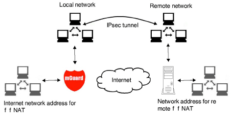
Figure 10-3: 1:1 NAT
|
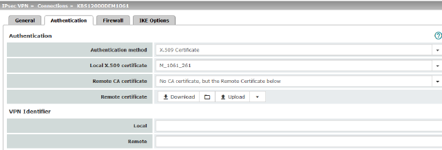
Authentication |
Authentication method |
There are two options: –X.509 Certificate (default setting) –Pre-shared key (PSK) The page contains different setting options depending on the method chosen. |
|
|
|
Authentication method: X.509 Certificate This method is supported by most modern IPsec implementations. With this option, each VPN device has a secret private key and a public key in the form of an X.509 certificate, which contains further information about the certificate's owner and the certification authority (CA). The following must be specified: –How the mGuard authenticates itself to the peer –How the mGuard authenticates the remote peer |
|
|
How the mGuard authenticates itself to the peer 
|
|
|
|
Local X.509 certificate (Authentication method: “X.509 Certificate”) |
Specifies which machine certificate the mGuard uses as authentication to the VPN peer. Select one of the machine certificates from the selection list. The selection list contains the machine certificates that have been loaded on the mGuard under the Authentication >> Certificates menu item. 
|
|
|
How the mGuard authenticates the remote peer |
|
|
|
The following definition relates to how the mGuard verifies the authenticity of the VPN remote peer. The table below shows which certificates must be provided for the mGuard to authenticate the VPN peer if the VPN peer shows one of the following certificate types when a connection is established: –A machine certificate signed by a CA –A self-signed machine certificate |
|
|
|
Remote CA certificate |
The following selection options are available: –Signed by any trusted CA –No CA certificate, but the Remote Certificate below –Name of a CA certificate if available |
|
|
Remote certificate (For authentication using remote certificate) |
You can upload the remote certificate. The certificate is selected and stored in the list of remote certificates (see "Remote Certificates" on page 254). |
For additional information about the table, see "Authentication >> Certificates" on page 243.
Authentication for VPN
|
The peer shows the following: |
Machine certificate, signed by CA |
Machine certificate, self-signed |
|
The mGuard authenticates the peer using: |
|
|
|
|
Remote certificate Or all CA certificates that form the chain to the root CA certificate together with the certificate shown by the peer |
Remote certificate |
According to this table, the certificates that must be provided are the ones the mGuard uses to authenticate the relevant VPN peer.
Requirements
The following instructions assume that the certificates have already been correctly installed on the mGuard (see "Authentication >> Certificates" on page 243, apart from the remote certificate).
|
If the use of revocation lists (CRL checking) is activated under the Authentication >> Certificates, Certificate Settings menu item, each certificate signed by a CA that is “shown” by the VPN peer is checked for revocations. However, an existing VPN connection is not immediately terminated by a withdrawn certificate if the CRL update is being performed during the existing VPN connection. Nevertheless, it is no longer possible to exchange keys again (rekeying) or restart the VPN connection. |
Self-signed machine certificate
If the VPN peer authenticates itself with a self-signed machine certificate:
•Select the following entry from the selection list:
“No CA certificate, but the Remote Certificate below”
•Install the remote certificate under Remote certificate (see "Installing the remote certificate" on page 345).
|
It is not possible to reference a remote certificate loaded under the Authentication >> Certificates menu item. |
Machine certificate signed by the CA
If the VPN peer authenticates itself with a machine certificate signed by a CA:
It is possible to authenticate the machine certificate shown by the peer as follows:
–Using CA certificates
–Using the corresponding remote certificate
Authentication using a CA certificate:
Only the CA certificate from the CA that signed the certificate shown by the VPN peer should be referenced here (selection from list). The additional CA certificates that form the chain to the root CA certificate together with the certificate shown by the peer must be installed on the mGuard under the Authentication >> Certificates menu item.
The selection list contains all CA certificates that have been loaded on the mGuard under the Authentication >> Certificates menu item.
The other option is “Signed by any trusted CA”.
With this setting, all VPN peers are accepted, providing they log in with a signed CA certificate issued by a recognized certification authority (CA). The CA is recognized if the relevant CA certificate and all other CA certificates have been loaded on the mGuard. These then form the chain to the root certificate together with the certificates shown.
Authentication using the corresponding remote certificate:
•Select the following entry from the selection list:
“No CA certificate, but the Remote Certificate below”
•Install the remote certificate under Remote certificate (see "Installing the remote certificate" on page 345).
|
It is not possible to reference a remote certificate loaded under the Authentication >> Certificates menu item. |
Installing the remote certificate
The remote certificate must be configured if the VPN peer is to be authenticated using a remote certificate.
To import a certificate, proceed as follows:
Requirement
The certificate file (file name extension: *.pem, *.cer or *.crt) is saved on the connected computer.
•No file selected... click to select the file
•Click on Upload.
The contents of the certificate file are then displayed.
|
IPsec VPN >> Connections >> Edit >> Authentication |
||
|---|---|---|
|
Authentication method: CA certificate The following explanation applies if the VPN peer is authenticated using CA certificates. VPN gateways use the VPN identifier to detect which configurations belong to the same VPN connection. If the mGuard consults CA certificates to authenticate a VPN peer, then it is possible to use the VPN identifier as a filter. •Make a corresponding entry in the Remote field. |
||
|
|
Local |
Default: empty field The local VPN identifier can be used to specify the name the mGuard uses to identify itself to the peer. It must match the data in the machine certificate of the mGuard. Valid values: –Empty, i.e., no entry (default). The “Subject” entry (previously Distinguished Name) in the machine certificate is then used. –The “Subject” entry in the machine certificate. –One of the Subject Alternative Names, if they are listed in the certificate. If the certificate contains Subject Alternative Names, these are specified under “Valid values:”. These can include IP addresses, host names with “@” prefix or e-mail addresses. |
|
|
Specifies what must be entered as a subject in the machine certificate of the VPN peer for the mGuard to accept this VPN peer as a communication partner. It is then possible to restrict or enable access by VPN peers, which the mGuard would accept in principle based on certificate checks, as follows: – Restricted access to certain subjects (i.e., machines) and/or to subjects that have certain attributes or – Access enabled for all subjects (See "Subject, certificate" on page 449.) 
|
|
|
|
Access enabled for all subjects: If the Remote field is left empty, then any subject entries are permitted in the machine certificate shown by the VPN peer. It is then no longer necessary to identify or define the subject in the certificate. Restricted access to certain subjects: In the certificate, the certificate owner is specified in the Subject field. The entry is comprised of several attributes. These attributes are either expressed as an object identifier (e.g., 132.3.7.32.1) or, more commonly, as an abbreviation with a corresponding value. Example: CN=VPN endpoint 01, O=Smith and Co., C=US If certain subject attributes have very specific values for the acceptance of the VPN peer by the mGuard, then these must be specified accordingly. The values of the other freely selectable attributes are entered using the * (asterisk) wildcard. Example: CN=*, O=Smith and Co., C=US (with or without spaces between attributes) In this example, the attributes “O=Smith and Co.” and “C=US” should be entered in the certificate that is shown under “Subject”. It is only then that the mGuard would accept the certificate owner (subject) as a communication partner. The other attributes in the certificates to be filtered can have any value. 
|
|
|
Authentication |
Authentication method: Pre-shared key (PSK) 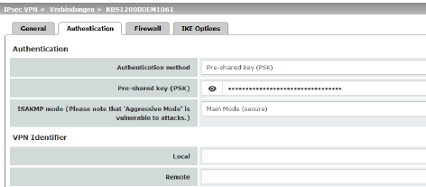
This method is mainly supported by older IPsec implementations. In this case, both sides of the VPN authenticate themselves using the same PSK. To make the agreed key available to the mGuard, proceed as follows: •Enter the agreed string in the Pre-shared key (PSK) input field. 


|
|
|
|
ISAKMP mode |
Main Mode (secure) In Main Mode, the party wishing to establish the connection (initiator) and the responder negotiate an ISAKMP SA. We recommend using certificates in Main Mode. Encryption for Aggressive Mode is not as secure as for Main Mode. The use of this mode can be justified if the responder does not know the initiator's address in advance, and both parties wish to use pre-shared keys for authentication. Another reason may be to achieve faster connection establishment when the responder's credentials are already known, e.g., an employee wishing to access the company network. Requirement: –Cannot be used together with the redundancy function. –The same mode must be used between peers. –Aggressive mode is not supported in conjunction with XAuth/Mode Config. –If two VPN clients downstream of the same NAT gateway establish the same connection to a VPN gateway, they must use the same PSK. |
|
VPN gateways use the VPN Identifier to detect which configurations belong to the same VPN connection. The following entries are valid for PSK: –Empty (IP address used by default) –An IP address –A host name with “@” prefix (e.g., “@vpn1138.example.com”) –An e-mail address (e.g., “piepiorra@example.com”) |
||
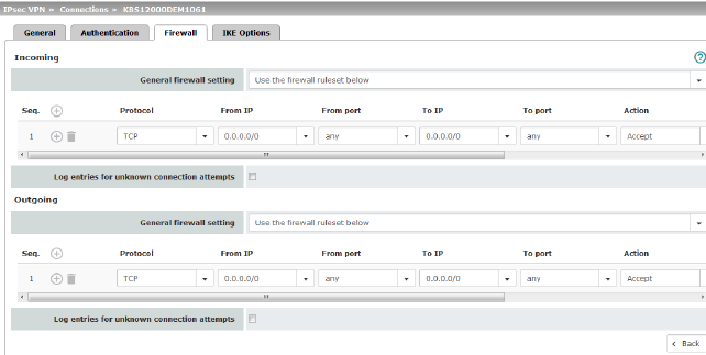
Incoming/outgoing firewall
While the settings made under the Network Security menu item only relate to non-VPN connections (see above under "Network Security menu" on page 259), the settings here only relate to the VPN connection defined on these tab pages.
If multiple VPN connections have been defined, you can restrict the outgoing or incoming access individually for each connection. Any attempts to bypass these restrictions can be logged.
|
By default, the VPN firewall is set to allow all connections for this VPN connection. However, the extended firewall settings defined and explained above apply independently for each individual VPN connection (see "Network Security menu" on page 259, "Network Security >> Packet Filter" on page 259, "Advanced" on page 278). |
|
If multiple firewall rules are defined, these are queried starting from the top of the list of entries until an appropriate rule is found. This rule is then applied. If the list of rules contains further subsequent rules that could also apply, these rules are ignored. |
|
In Stealth mode, the actual IP address used by the client should be used in the firewall rules, or it should be left at 0.0.0.0/0, as only one client can be addressed through the tunnel. |
|
If the Allow packet forwarding between VPN connections function is activated on the Global tab page, the rules under Incoming are used for the incoming data packets to the mGuard, and the rules under Outgoing are applied to the outgoing data packets. If the outgoing data packets are included in the same connection definition (for a defined VPN connection group), then the firewall rules for Incoming and Outgoing for the same connection definition are used. If a different VPN connection definition applies to the outgoing data packets, the firewall rules for Outgoing for this other connection definition are used. |
|
If the mGuard has been configured to forward SSH connection packets (e.g., by permitting a SEC-Stick hub & spoke connection), existing VPN firewall rules are not applied. This means, for example, that packets of an SSH connection are sent through a VPN tunnel despite the fact that this is prohibited by its firewall rules. |
|
Incoming |
General firewall setting |
Accept all incoming connections: the data packets of all incoming connections are allowed. Drop all incoming connections: the data packets of all incoming connections are discarded. Accept Ping only: the data packets of all incoming connections are discarded, except for ping packets (ICMP). Use the firewall ruleset below: displays further setting options. |
|
|
The following settings are only visible if “Use the firewall ruleset below” is set. |
|
|
|
Protocol |
All means TCP, UDP, ICMP, GRE, and other IP protocols. |
|
|
From IP/To IP |
0.0.0.0/0 means all IP addresses. To specify an address area, use CIDR format (see "CIDR (Classless Inter-Domain Routing)" on page 29). Name of IP groups, if defined. When a name is specified for an IP group, the host names, IP addresses, IP areas or networks saved under this name are taken into consideration (see "IP/Port Groups" on page 276). 

Incoming: –From IP: IP address in the VPN tunnel –To IP: 1:1 NAT address or the actual address Outgoing: –From IP: 1:1 NAT address or the actual address –To IP: IP address in the VPN tunnel |
|
|
From port / To port (Only for TCP and UDP protocols) |
any refers to any port. startport:endport (e.g., 110:120) refers to a port range. Individual ports can be specified using the port number or the corresponding service name (e.g., 110 for pop3 or pop3 for 110). Name of port groups, if defined. When a name is specified for a port group, the ports or port ranges saved under this name are taken into consideration (see "IP/Port Groups" on page 276). |
|
|
Action |
Accept means that the data packets may pass through. Reject means that the data packets are sent back and the sender is informed of their rejection. (In Stealth mode, Reject has the same effect as Drop.) Drop means that the data packets are not permitted to pass through. They are discarded, which means that the sender is not informed of their whereabouts. Name of rule sets, if defined. When a name is specified for rule sets, the firewall rules configured under this name take effect (see "Rule Records" on page 270 tab page). 

Name of Modbus TCP rule sets, if defined. When a Modbus TCP rule set is selected, the firewall rules configured under this rule set take effect (see "Modbus TCP" on page 283). |
|
|
Freely selectable comment for this rule. |
|
|
|
Log |
For each individual firewall rule, you can specify whether the use of the rule: –Should be logged – activate Log function –Should not be logged – deactivate Log function (default) |
|
|
Log entries for unknown connection attempts |
When the function is activated, all connection attempts that are not covered by the rules defined above are logged. |
|
Outgoing |
The explanation provided under “Incoming” also applies to “Outgoing”. |
|
10.3IPsec VPN >> L2TP via IPsec
|
These settings do not apply in Stealth mode. It is not possible to use the MD5 algorithm under Windows 7. The MD5 algorithm must be replaced by SHA-1. |
Allows VPN connections to the mGuard to be established using the IPsec/L2TP protocol.
In doing so, the L2TP protocol is driven using an IPsec transport connection in order to establish a tunnel connection to a Point-to-Point Protocol (PPP). Clients are automatically assigned IP addresses by the PPP.
In order to use IPsec/L2TP, the L2TP server must be activated and one or more IPsec connections with the following properties must be defined:
–Type: Transport
–Protocol: UDP
–Local: %all
–Remote: %all
–PFS: No
See
–IPsec VPN >> Connections >> Edit >> General on Page 324
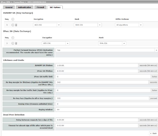
–IPsec VPN >> Connections >> Edit >> IKE Options, Perfect Forward Secrecy (PFS) on Page 355
|
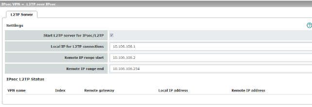
If you want to enable IPsec/L2TP connections, activate the function. It is then possible to establish L2TP connections to the mGuard via IPsec, which dynamically assign IP addresses to the clients within the VPN. |
||
|
|
Local IP for L2TP connections |
If set as shown in the screenshot above, the mGuard will inform the peer that its address is 10.106.106.1. |
|
|
Remote IP range start/end |
If set as shown in the screenshot above, the mGuard will assign the peer an IP address between 10.106.106.2 and 10.106.106.254. |
|
|
Displays information about the L2TP status if this connection type has been selected. |
|
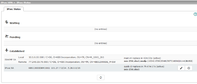
Displays information about the current status of the configured IPsec connections.
Waiting: displays all VPN connections that have not yet been established which will be started by means of initiation on data traffic or which are waiting for a connection to be established.
Pending: displays all VPN connections that are currently attempting to establish a connection.
The ISAKMP SA has been established and authentication of the connections was completed successfully. If the connection remains in “connection establishment” status the other parameters may not match: does the connection type (Tunnel, Transport) correspond? If “Tunnel” is selected, do the network areas match on both sides?
Established: displays all VPN connections that have successfully established a connection.
The VPN connection has been successfully established and can be used. However, if this is not possible, the VPN gateway of the peer is causing problems. In this case, deactivate and reactivate the connection to reestablish the connection.
Icons
Reload
To update the displayed data, click on the  Reload icon.
Restart
Click on the Restart button  if you want to disconnect a line and restart.
Edit
Click on the corresponding  icon Edit rows to reconfigure a connection.
Connection, ISAKMP SA Status, IPsec SA Status
|
ISAKMP SA |
Local |
–Local IP address –Local port –ID = subject of an X.509 certificate |
State, lifetime, and encryption algorithm for the connection (bold = active) |
|
|
Remote |
–Remote IP address –Local port –ID = subject of an X.509 certificate |
|
|
IPsec SA |
|
–Name of the connection –Local networks ... Remote networks |
State, lifetime, and encryption algorithm for the connection (bold = active) |
In the event of problems, it is recommended that you check the VPN logs of the peer to which the connection was established. This is because detailed error messages are not forwarded to the initiating computer for security reasons.