Default setting for TC MGUARD RS4000/RS2000 4G, TC MGUARD RS4000/RS2000 3G, FL MGUARD RS4004/RS2005, FL MGUARD GT/GT, mGuard Centerport (Innominate), FL MGUARD CENTERPORT, FL MGUARD BLADE-Controller, mGuard delta (Innominate)
The mGuard has the following interfaces with external access:
|
|
Ethernet: internal: LAN external: WAN |
Serial interface |
Built-in modem |
Serial console via USB1 |
|
FL MGUARD RS4000/RS2000 |
Yes |
Yes |
No |
No |
|
FL MGUARD RS4004 |
LAN: 4 |
Yes |
No |
No |
|
FL MGUARD RS2005 |
LAN: 5 |
Yes |
No |
No |
|
TC MGUARD RS4000 3G, TC MGUARD RS4000 4G |
LAN: 4 |
Yes |
Yes |
No |
|
TC MGUARD RS2000 3G, TC MGUARD RS2000 4G |
LAN: 4 |
Yes |
Yes |
No |
|
FL MGUARD CENTERPORT |
LAN: 1 |
Yes |
No |
No |
|
FL MGUARD SMART2 |
Yes |
No |
No |
Yes |
|
FL MGUARD GT/GT, FL MGUARD RS, FL MGUARD PCI 533/266, FL MGUARD BLADE, FL MGUARD DELTA, mGuard Centerport (Innominate), mGuard delta (Innominate) |
Yes |
Yes |
No |
No |
|
FL MGUARD PCI(E)4000 |
Yes |
No |
No |
No |
|
FL MGUARD RS |
Yes |
Yes |
Yes |
No |
|
FL MGUARD SMART 533/266 |
Yes |
No |
No |
No |
The LAN port is connected to a stand-alone computer or the local network (internal). The WAN port is used to connect to the external network. For devices with a serial interface, the connection to the external network can also or additionally be established via the serial interface using a modem. Alternatively, the serial interface can also be used as follows: for PPP dial-in into the local network or for configuration purposes. For devices with a built-in modem (analog modem or ISDN terminal adapter), the modem can also be used to combine access options.
The details for this must be configured on the General, Dial-out, Dial-in and Modem/Console tabs. For a more detailed explanation of the options for using the serial interface (and a built-in modem), see "Modem" on page 186.
Connecting the network interface
The mGuard platforms have DTE interfaces. Connect the mGuards to the DTE interface using an Ethernet crossover cable. Here auto MDIX is permanently switched on, so it does not matter if the auto negotiation parameter is disabled.
6.1.1Overview of "Router" network mode
|
Default setting for TC MGUARD RS4000/RS2000 4G, TC MGUARD RS4000/RS2000 3G, FL MGUARD RS4004/RS2005, FL MGUARD GT/GT, mGuard Centerport (Innominate), FL MGUARD CENTERPORT, FL MGUARD BLADE-Controller, mGuard delta (Innominate) |
If the mGuard is in Router mode, it acts as the gateway between various subnetworks and has both an external interface (WAN port) and an internal interface (LAN port) with at least one IP address.
WAN port
The mGuard is connected to the Internet or other “external” parts of the LAN via its WAN port.
–FL MGUARD SMART2: the WAN port is the Ethernet socket.
LAN port
The mGuard is connected to a local network or a stand-alone computer via its LAN port:
–FL MGUARD SMART2: the LAN port is the Ethernet connector.
–In Power-over-PCI mode, the LAN port is the LAN socket of the FL MGUARD PCI(E)4000, FL MGUARD PCI(E)4000, FL MGUARD PCI 533/266.
As in the other modes, firewall and VPN security functions are available (depending on license).
|
If the mGuard is operated in Router mode, it must be set as the default gateway on the locally connected computers. This means that the IP address of the mGuard LAN port must be specified as the default gateway address on these computers. |
|
NAT should be activated if the mGuard is operated in Router mode and establishes the connection to the Internet (see "Network >> NAT" on page 198). Only then can the computers in the connected local network access the Internet via the mGuard. If NAT is not activated, it is possible that only VPN connections can be used. |
In Router network mode, a secondary external interface can also be configured (see "Secondary External Interface" on page 152).
There are several Router modes, depending on the Internet connection:
–Static
–DHCP
–PPPoE
–PPPT
–Modem
–Built-in modem / Built-in mobile network modem
The external IP-settings are fixed.
The external IP-settings are requested by the mGuard and assigned by an external DHCP server.
PPPoE mode corresponds to Router mode with DHCP but with one difference: the PPPoE protocol, which is used by many DSL modems (for DSL Internet access), is used to connect to the external network (Internet, WAN). The external IP address, which the mGuard uses for access from remote peers, is specified by the provider.
|
If the mGuard is operated in PPPoE mode, the mGuard must be set as the default gateway on the locally connected computers. This means that the IP address of the mGuard LAN port must be specified as the default gateway address on these computers. |
|
If the mGuard is operated in PPPoE mode, NAT must be activated in order to access the Internet. If NAT is not activated, it is possible that only VPN connections can be used. |
For the further configuration of PPPoE network mode, see "PPPoE" on page 144.
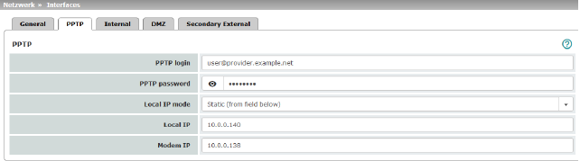
Similar to PPPoE mode. For example, in Austria the PPTP protocol is used instead of the PPPoE protocol for DSL connections.
(PPTP is the protocol that was originally used by Microsoft for VPN connections.)
|
If the mGuard is operated in PPTP mode, the mGuard must be set as the default gateway on the locally connected computers. This means that the IP address of the mGuard LAN port must be specified as the default gateway on these computers. |
|
If the mGuard is operated in PPTP mode, NAT should be activated in order to access the Internet from the local network (see "Network >> NAT" on page 198). If NAT is not activated, it is possible that only VPN connections can be used. |
For the further configuration of PPTP network mode, see "PPTP" on page 145.
|
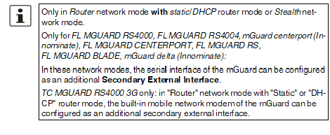
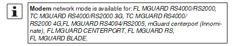
Only for FL MGUARD RS4000/RS2000, TC MGUARD RS4000/RS2000 3G, TC MGUARD RS4000/RS2000 4G, FL MGUARD RS4004/RS2005, mGuard Centerport (Innominate), FL MGUARD CENTERPORT, FL MGUARD RS, FL MGUARD BLADE, mGuard delta (Innominate), FL MGUARD DELTA |
If Modem network mode is selected, the external Ethernet interface of the mGuard is deactivated and data traffic is transferred to and from the WAN via the externally accessible serial interface (serial port) of the mGuard.
An external modem, which establishes the connection to the telephone network, is connected to the serial interface. The connection to the WAN or Internet is then established via the telephone network (by means of the external modem).
|
If the address of the mGuard is changed (e.g., by changing the network mode from Stealth to Router), the device can only be accessed via the new address. If the configuration is changed via the LAN port, confirmation of the new address is displayed before the change is applied. If configuration changes are made via the WAN port, no confirmation is displayed. |
|
If the mode is set to Router, PPPoE or PPTP and you then change the IP address of the LAN port and/or the local netmask, make sure you specify the correct values. Otherwise, the mGuard may no longer be accessible under certain circumstances. For the further configuration of Built-in mobile network modem / Built-in modem / Modem network mode, see "Dial-out" on page 177. |
After selecting Modem as the network mode, specify the required parameters for the modem connection on the Dial-out and/or Dial-in tab (see "Dial-out" on page 177 and "Dial-in" on page 183).
In Modem network mode, the serial interface of the mGuard is not available for the PPP dial-in option or for configuration purposes (see "Modem" on page 186).
Enter the connection settings for an external modem on the Modem tab page (see "Modem" on page 186).
|
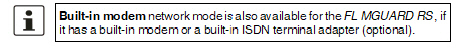
Only used for FL MGUARD RS devices with a built-in modem or ISDN terminal adapter. |
If Built-in modem network mode is selected, the external Ethernet interface of the mGuard is deactivated and data is transferred to and from the WAN via the built-in modem or built-in ISDN terminal adapter of the mGuard. This must be connected to the telephone network. The connection to the Internet is then established via the telephone network.
After selecting Built-in modem, the fields for specifying the modem connection parameters are displayed.
For the further configuration of Built-in modem / Modem network mode (see "Dial-out" on page 177).
Router Mode: Built-in mobile network modem
|
Only for TC MGUARD RS4000/RS2000 3G and TC MGUARD RS4000/RS2000 4G. |
If Built-in mobile network modem is selected as the network mode, data traffic is routed via the built-in mobile network modem instead of the WAN port of the mGuard.
For the further configuration of Built-in modem / Modem network mode (see "Dial-out" on page 177).
6.1.2Overview of "Stealth" network mode
|
Default setting for FL MGUARD RS4000/RS2000, FL MGUARD RS, FL MGUARD SMART2, FL MGUARD PCI(E)4000, FL MGUARD PCI(E)4000, FL MGUARD PCI 533/266, FL MGUARD DELTA |
Stealth mode (Plug-n-Protect) is used to protect a stand-alone computer or a local network with the mGuard. Important: if the mGuard is in Stealth network mode, it is inserted into the existing network (see figure) without changing the existing network configuration of the connected devices.
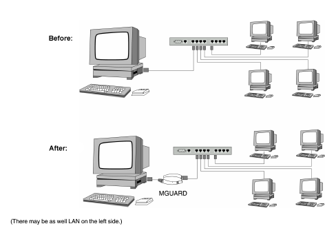
The mGuard analyzes the network traffic and independently configures its network connection accordingly. It works transparently and therefore cannot be detected in the network without configured management IP address. Connected computers keep their network configuration and must not be reconfigured.
As in the other modes, firewall and VPN security functions are available (depending on licence).
Externally supplied DHCP data is allowed through to the connected computer.
|
In Single-Stealth mode, a firewall installed on the computer must be configured to allow ICMP echo requests (ping), if the mGuard is to provide services such as VPN, DNS, NTP, etc. |
|
In Stealth mode, the mGuard uses internal IP address 1.1.1.1. This can be accessed from the computer if the default gateway configured on the computer is accessible. |
|
In the Stealth configurations "Autodetect" and "Static", it is not possible to establish a VPN-connection originating from the internal client through the mGuard. |
In Stealth network mode, a secondary external interface can also be configured (see "Secondary External Interface" on page 152).
Stealth configurations
Autodetect
The mGuard analyzes the outgoing network traffic and independently configures its network connection accordingly. It operates transparently.
|
For the use of certain functions (e.g. automatic updates, licence updates or establishment of VPN-connections), it is required that the mGuard makes its own requests of external servers, even in stealth mode. These requests are only possible when the locally connected computer permits ping requests. Configure its security settings accordingly. |
Static
If the mGuard cannot analyze the network traffic, e.g., because the locally connected computer only receives data and does not send it, then Stealth configuration must be set to Static. In this case, further input fields are available for Static Stealth Configuration.
Multiple clients (default setting)
As with Autodetect, but it is possible to connect more than one computer to the LAN port (secure port) of the mGuard, meaning that multiple IP addresses can be used at the LAN port (secure port) of the mGuard.
For the further configuration of Stealth network mode, see "Stealth" on page 148.

|
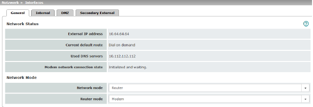
Network Status |
External IP address |
Display only: the addresses via which the mGuard can be accessed by devices from the external network. They form the interface to other parts of the LAN or to the Internet. If the transition to the Internet takes place here, the IP addresses are usually assigned by the Internet service provider (ISP). If an IP address is assigned dynamically to the mGuard, the currently valid IP address can be found here. In Stealth mode, the mGuard adopts the address of the locally connected computer as its external IP. |
|
|
Secondary external IP address (Only if the secondary external interface is activated) |
Display only: the addresses via which the mGuard can be accessed by devices from the external network via the secondary external interface. |
|
|
Current default route |
Display only: the IP address that the mGuard uses to try to reach unknown networks is displayed here. If a default route has not been specified, the field is left empty. |
|
|
Used DNS servers |
Display only: the names of the DNS servers used by the mGuard for name resolution are displayed here. This information can be useful, for example, if the mGuard is using the DNS servers assigned to it by the Internet service provider. |
|
|
Connection status of modem to data network (Only for devices with an internal modem) |
Displays the status of the internal modem (mobile network modem of the TC MGUARD RS4000/RS2000 3G / TC MGUARD RS4000/RS2000 4G and the internal analog modem for the FL MGUARD RS). |
|
Network mode |
Network mode |
Router / Stealth The mGuard must be set to the network mode that corresponds to its connection to the network 
. See also: "Overview of "Router" network mode" on page 132 and "Overview of "Stealth" network mode" on page 135. |
|
|
Depending on the network mode selected and the mGuard device, different setting options are available on the web interface: |
|
|
|
Router Mode (Only if "Router" network mode was selected) |
Static / DHCP / PPPoE / PPTP / Modem1 / Built-in modem1 / Built-in mobile network modem1 For a detailed description, see: –"Router Mode: Static" on page 133 –"Router Mode: DHCP" on page 133 –"Router Mode: PPPoE" on page 133 and "PPPoE" on page 144 –"Router Mode: PPTP" on page 133 and "PPTP" on page 145 –"Router Mode: Modem" on page 133 and "Dial-out" on page 177 |
|
|
(Only if "Stealth" network mode was selected) |
Autodetect / Static / Multiple clients Autodetect The mGuard analyzes the network traffic and independently configures its network connection accordingly. It operates transparently. 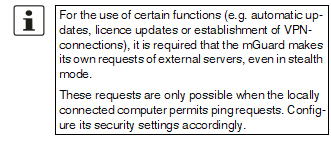
Static If the mGuard cannot analyze the network traffic, e.g., because the locally connected computer only receives data and does not send it, then Stealth configuration must be set to Static. In this case, further input fields are available for Static Stealth Configuration at the bottom of the page. Multiple clients (Default) As with Autodetect, but it is possible to connect more than one computer to the LAN port (secure port) of the mGuard, meaning that multiple IP addresses can be used at the LAN port (secure port) of the mGuard. |
|
|
||
|
|
||
|
|
||
|
|
Autodetect: ignore NetBIOS over TCP traffic on TCP port 139 (Only with Autodetect Stealth configuration) |
If a Windows computer has more than one network card installed, it may alternate between the different IP addresses for the sender address in the data packets it sends. This applies to network packets that the computer sends to TCP port 139 (NetBIOS). As the mGuard determines the address of the computer from the sender address (and therefore the address via which the mGuard can be accessed), the mGuard would have to switch back and forth, and this would hinder operation considerably. To avoid this, activate the function if the mGuard has been connected to a computer that has these properties. |
|
1Modem / Built-in modem / Built-in mobile network modem is not available for all mGuard models (see "Network >> Interfaces" on page 131). |
|
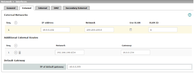
Network >> Interfaces >> External (network mode = "Router", router mode = "Static") |
||
|---|---|---|
|
The addresses via which the mGuard can be accessed by external devices that are located behind the WAN port. If the transition to the Internet takes place here, the external IP address of the mGuard is assigned by the Internet service provider (ISP). |
||
|
|
IP address |
IP address via which the mGuard can be accessed via its WAN port. |
|
|
Netmask |
The netmask of the network connected to the WAN port. |
|
|
Use VLAN |
If the IP address should be within a VLAN, activate the function. |
|
|
VLAN ID |
–A VLAN ID between 1 and 4095. –For an explanation of the term "VLAN", please refer to the glossary on page 452. –If you want to delete entries from the list, please note that the first entry cannot be deleted. |
|
|
OSPF area (Only if OSPF is activated) |
Links the static addresses/routes of the internal network interface to an OSPF area (see "Network >> Dynamic Routing" on page 220). 
|
|
In addition to the default route via the default gateway specified below, additional external routes can be specified. |
||
|
|
Network |
Specify the network in CIDR format (see "Network >> Dynamic Routing" on page 220). |
|
|
Gateway |
The gateway via which this network can be accessed. See also "Network example diagram" on page 30. |
|
Default gateway |
The IP address of a device in the local network (connected to the LAN port) or the IP address of a device in the external network (connected to the WAN port) can be specified here. If the mGuard establishes the transition to the Internet, this IP address is assigned by the Internet service provider (ISP). If the mGuard is used within the LAN, the IP address of the default gateway is assigned by the network administrator. 
|
|
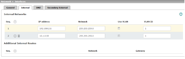
|
IP address |
The internal IP is the IP address via which the mGuard can be accessed by devices in the locally connected network. The default settings in Router/PPPoE/PPTP/Modem mode are as follows: –IP address: 192.168.1.1 –Netmask: 255.255.255.0 You can also specify other addresses via which the mGuard can be accessed by devices in the locally connected network. For example, this can be useful if the locally connected network is divided into subnetworks. Multiple devices in different subnetworks can then access the mGuard via different addresses. |
|
|
|
IP address |
IP address via which the mGuard can be accessed via its LAN port. |
|
|
Netmask |
The netmask of the network connected to the LAN port. |
|
|
Use VLAN |
If the IP address should be within a VLAN, activate the function. |
|
|
–A VLAN ID between 1 and 4095. –For an explanation of the term "VLAN", please refer to the glossary on page 452. –If you want to delete entries from the list, please note that the first entry cannot be deleted. |
|
|
|
OSPF area (Only if OSPF is activated) |
Links the static addresses/routes of the internal network interface to an OSPF area (see "Network >> Dynamic Routing" on page 220). 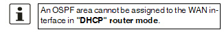
|
|
Additional Internal Routes |
Additional routes can be defined if further subnetworks are connected to the locally connected network. |
|
|
|
Network |
Specify the network in CIDR format (see "CIDR (Classless Inter-Domain Routing)" on page 29). |
|
|
The gateway via which this network can be accessed. See also "Network example diagram" on page 30. |
|
|
Network >> Interfaces >> PPPoE (Network mode = "Router", router mode = "PPPoE") |
||
|---|---|---|
|
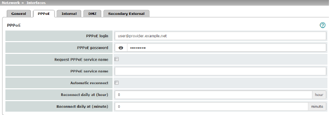
PPPoE |
For access to the Internet, the Internet service provider (ISP) provides the user with a user identifier (login) and password. These are requested when you attempt to establish a connection to the Internet. |
|
|
|
PPPoE login |
The user identifier (login) that is required by the Internet service provider (ISP) when you attempt to establish a connection to the Internet. |
|
|
PPPoE password |
The password that is required by the Internet service provider when you attempt to establish a connection to the Internet. |
|
|
Request PPPoE service name |
When the function is activated, the PPPoE client of the mGuard requests the service name specified below from the PPPoE server. Otherwise, the PPPoE service name is not used. |
|
|
PPPoE service name |
PPPoE service name |
|
|
Automatic Reconnect |
When the function is activated, you must specify the time in the Reconnect daily at field. This feature is used to schedule Internet disconnection and reconnection (as required by many Internet service providers) so that they do not interrupt normal business operations. When this function is enabled, it only takes effect if synchronization with a time server has been carried out (see "Management >> System Settings" on page 47, "Time and Date" on page 49). |
|
|
Reconnect daily at (hour) |
Specified time (hour) at which the Automatic Reconnect function (see above) should be performed. |
|
|
Reconnect daily at (minute) |
Specified time (minute) at which the Automatic Reconnect function (see above) should be performed. |
|
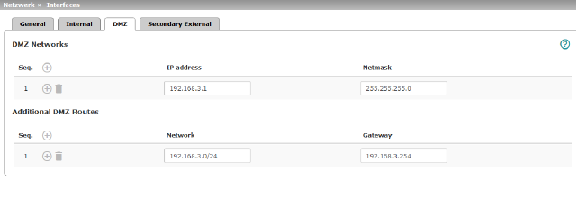
Network >> Interfaces >> DMZ (Network mode = "Router") |
||
|---|---|---|
|
(Only for TC MGUARD RS4000 3G, TC MGUARD RS4000 4G, FL MGUARD RS4004, FL MGUARD CENTERPORT) |
IP addresses |
IP address via which the mGuard can be accessed by devices in the network connected to the DMZ port. 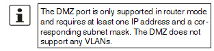
In "Router" network mode, every newly added table line has default settings: –IP address: 192.168.3.1 –Netmask: 255.255.255.0 You can also specify other addresses via which the mGuard can be accessed by devices in the networks connected to the DMZ port. For example, this can be useful if the network connected to the DMZ port is divided into subnetworks. Multiple devices in different subnetworks can then access the mGuard via different addresses. |
|
|
IP address |
IP address via which the mGuard can be accessed via its DMZ port. Default: 192.168.3.1 |
|
|
Netmask |
The netmask of the network connected to the DMZ port. Default: 255.255.255.0 |
|
|
OSPF area (Only if OSPF is activated) |
Links the static addresses/routes of the DMZ network interface to an OSPF area (see "Network >> Dynamic Routing" on page 220). 
|
|
Additional DMZ Routes |
Additional routes can be defined if further subnetworks are connected to the DMZ. |
|
|
|
Network |
Specify the network in CIDR format (see "CIDR (Classless Inter-Domain Routing)" on page 29). Default: 192.168.3.0/24 |
|
|
Gateway |
The gateway via which this network can be accessed. See also "Network example diagram" on page 30. Default: 192.168.3.254 |
|
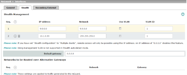
Additional Management IP addresses for the administration of the mGuard can be specified here. If: –The Multiple clients option is selected under Stealth configuration –The client does not answer ARP requests –No client is available Remote access via HTTPS, SNMP, and SSH is only possible using this address. 
|
||
|
|
Management IP address via which the mGuard can be accessed and administered. 
The IP address "0.0.0.0" deactivates the management IP address. Change the management IP address first before specifying any additional addresses. |
|
|
|
Netmask |
The netmask of the IP address above. |
|
|
Use VLAN |
IP address and netmask of the VLAN port. If the IP address should be within a VLAN, activate the function. 
|
|
|
VLAN ID |
This option only applies if you set the "Stealth configuration" option to "Multiple clients". –A VLAN ID between 1 and 4095. –An explanation can be found under "VLAN" on page 452. –If you want to delete entries from the list, please note that the first entry cannot be deleted. 
|
|
|
The default gateway of the network where the mGuard is located. 
|
|
|
Networks to be routed over alternative gateways |
In Stealth modes "Autodetect" and "Static", the mGuard adopts the default gateway of the computer connected to its LAN port. This does not apply if a management IP address is configured with the default gateway. Alternative routes can be specified for data packets destined for the WAN that have been created by the mGuard. These include for instance the packets from the following types of data traffic: –Download of certificate revocation lists (CRLs) –Download of a new configuration –Communication with an NTP server (for time synchronization) –Sending and receiving encrypted data packets from VPN connections –Requests to DNS servers –Log messages –Download of firmware updates –Download of configuration profiles from a central server (if configured) –SNMP traps |
|
|
|
If this option is used, make the relevant entries afterwards. If it is not used, the affected data packets are routed via the default gateway specified for the client. 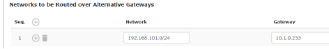
|
|
|
|
Network |
Specify the network in CIDR format (see "CIDR (Classless Inter-Domain Routing)" on page 29). |
|
|
Gateway |
The gateway via which this network can be accessed. The routes specified here are mandatory routes for data packets created by the mGuard. This setting has priority over other settings (see also "Network example diagram" on page 30). |
|
Settings for Stealth mode (static) |
Client IP address |
The IP address of the computer connected to the LAN port. |
|
|
The physical address of the network card of the local computer to which the mGuard is connected. •The MAC address can be determined as follows: In DOS (Start, All Programs, Accessories, Command Prompt), enter the following command: ipconfig /all |
|
|
|
|
The MAC address does not necessarily have to be specified. The mGuard can automatically obtain the MAC address from the client. The MAC address 0:0:0:0:0:0 must be set in order to do this. Please note that the mGuard can only forward network packets to the client once the MAC address of the client has been determined. If no Stealth Management IP Address or Client MAC address is configured in static Stealth mode, then DAD ARP requests are sent via the internal interface (see RFC 2131, "Dynamic Host Configuration Protocol", Section 4.4.1). |
6.1.10Secondary External Interface
|
Network >> Interfaces >> Secondary External Interface |
||
|---|---|---|
|
(Not for TC MGUARD RS2000 3G, TC MGUARD RS2000 4G, FL MGUARD RS2005, FL MGUARD RS2000) |
The secondary external interface can be used to transfer data traffic permanently or temporarily to the external network (WAN). If the secondary external interface is activated, the following applies: |
|
|
|
In Stealth network mode Only the data traffic generated by the mGuard is subject to the routing specified for the secondary external interface, not the data traffic from a locally connected computer. Locally connected computers cannot be accessed remotely either; only the mGuard itself can be accessed remotely – if the configuration permits this. As in Router network mode, VPN data traffic can flow to and from the locally connected computers. Because this traffic is encrypted by the mGuard, it is seen as being generated by the mGuard. |
|
|
|
In Router network mode All data traffic, i.e., from and to locally connected computers, generated by the mGuard, can be routed to the external network (WAN) via the secondary external interface. |
|
|
|
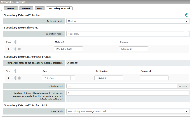
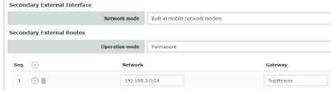
Network mode |
Off / Modem / Built-in mobile network modem Off (Default). Select this setting if the operating environment of the mGuard does not require a secondary external interface. You can then use the serial interface (or the built-in modem, if present) for other purposes (see "Modem" on page 186). Modem/Built-in modem If you select one of these options, the secondary external interface will be used to route data traffic permanently or temporarily to the external network (WAN). The secondary external interface is created via the serial interface of the mGuard and an external modem connected to it. Built-in mobile network modem Firmware 5.2 or later supports an external or internal modem as a fallback for the external interface. From Version 8.0, this also includes the internal mobile network modem of the TC MGUARD RS4000 3G. The modem can be used permanently as the secondary external interface. In the event of a network error, it can also be used temporarily as a secondary external interface. It supports dedicated routes and DNS configuration. |
|
Secondary External Routes (Not for TC MGUARD RS2000 3G, TC MGUARD RS2000 4G, FL MGUARD RS2005, FL MGUARD RS2000) |
Notes on the Permanent / Temporary operation modes: In both Permanent and Temporary mode, the modem must be available to the mGuard for the secondary external interface so that the mGuard can establish a connection to the WAN (Internet) via the telephone network connected to the modem. Which data packets are routed via the primary external interface (Ethernet interface) and which data packets are routed via the secondary external interface is determined by the routing settings that are applied for these two external interfaces. Therefore an interface can only take a data packet if the routing setting for that interface matches the destination of the data packet. 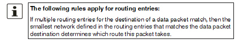
|
|
|
|
Permanent / Temporary After selecting Modem, Built-in modem or Built-in mobile network modem network mode for the secondary external interface, the operating mode of the secondary external interface must be specified (see "Example of use of routing entries:" on page 158). |
|
|
|
|
|
|
|
|
Permanent Data packets whose destination corresponds to the routing settings specified for the secondary external interface are always routed via this external interface. The secondary external interface is always activated. |
|
|
|
Temporary Data packets whose destination corresponds to the routing settings specified for the secondary external interface are only routed via this external interface when additional, separately defined conditions are met. Only then is the secondary external interface activated and the routing settings for the secondary external interface take effect (see "Secondary External Interface Probes" on page 156). |
|
|
Network |
Specify the routing to the external network here. Multiple routes can be specified. Data packets intended for these networks are then routed to the corresponding network via the secondary external interface – in permanent or temporary mode. |
|
|
Gateway |
Specify the IP address (if known) of the gateway that is used for routing to the external network described above. When you dial into the Internet using the phone number of the Internet service provider, the address of the gateway is usually not known until you have dialed in. In this case, enter %gateway in the field as a placeholder. |
|
Secondary External Interface Probes (Only Temporary operation mode) |
If the operating mode of the secondary external interface is set to Temporary, the following is checked using periodic ping tests: can a specific destination or destinations be reached when data packets take the route based on all the routing settings specified for the mGuard – apart from those specified for the secondary external interface? Only if none of the ping tests are successful does the mGuard assume that it is currently not possible to reach the destination(s) via the primary external interface (Ethernet interface or WAN port of the mGuard). In this case, the secondary external interface is activated, which results in the data packets being routed via this interface (according to the routing setting for the secondary external interface). The secondary external interface remains activated until the mGuard detects in subsequent ping tests that the destination(s) can be reached again. If this condition is met, the data packets are routed via the primary external interface again and the secondary external interface is deactivated. Therefore, the purpose of the ongoing ping tests is to check whether specific destinations can be reached via the primary external interface. When they cannot be reached, the secondary external interface is activated until they can be reached again. Successful ping test A ping test is successful if the mGuard receives a positive response to the sent ping request packet within 4 seconds. If the response is positive, the peer can be reached. 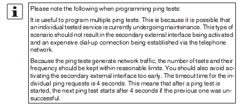
|
|
|
|
Specify the ping type of the ping request packet that the mGuard is to send to the device with the IP address specified under Destination. Multiple ping tests can be configured for different destinations. |
|
|
|
|
IKE ping Determines whether a VPN gateway can be reached at the IP address specified. ICMP ping Determines whether a device can be reached at the IP address specified. This is the most common ping test. However, the response to this ping test is disabled on some devices. This means that they do not respond even though they can be reached. DNS ping Determines whether an operational DNS server can be reached at the IP address specified. A generic request is sent to the DNS server with the specified IP address, and every DNS server that can be reached responds to this request. |
|
|
Target |
IP address of the probe target. |
|
|
Probe interval (seconds) |
The ping tests defined above under Probes for activation... are performed one after the other. When the ping tests defined are performed once in sequence, this is known as a test run. Test runs are continuously repeated at intervals. The interval entered in this field specifies how long the mGuard waits after starting a test run before it starts the next test run. The test runs are not necessarily completed: as soon as one ping test in a test run is successful, the subsequent ping tests in this test run are omitted. If a test run takes longer than the interval specified, then the subsequent test run is started directly after it. |
|
|
Number of times all probes need to fail during subsequent runs before the secondary external interface is activated |
Specifies how many sequentially performed test runs must return a negative result before the mGuard activates the secondary external interface. The result of a test run is negative if none of the ping tests it contains were successful. The number specified here also indicates how many consecutive test runs must be successful after the secondary external interface has been activated before this interface is deactivated again. |
|
DNS settings for the secondary external interface |
DNS Mode |
Only relevant if the secondary external interface is activated in Temporary mode: The DNS mode selected here specifies which DNS server the mGuard uses for temporary connections established via the secondary external interface. |
|
|
|
Use primary DNS settings untouched The DNS servers defined under Network >> DNS Server (see "Network >> DNS" on page 205) are used. DNS root servers Requests are sent to the root name servers on the Internet whose IP addresses are stored on the mGuard. These addresses rarely change. Provider-defined (via PPP dial-out) The domain name servers of the Internet service provider that provide access to the Internet are used. User-defined (servers listed below) If this setting is selected, the mGuard will connect to the domain name servers listed under User-defined name servers. |
|
|
DNS server (Only user-defined for DNS mode) |
The IP addresses of domain name servers can be entered in this list. The mGuard uses this list for communication via the secondary external interface if this is activated temporarily. |
Example of use of routing entries:
–The external route of the primary external interface is specified as 10.0.0.0/8, while the external route of the secondary external interface is specified as 10.1.7.0/24. Data packets to network 10.1.7.0/24 are then routed via the secondary external interface, although the routing entry for the primary external interface also matches them. Explanation: the routing entry for the secondary external interface refers to a smaller network (10.1.7.0/24 < 10.0.0.0/8).
–This rule does not apply in Stealth network mode with regard to the stealth management IP address (see note under "Stealth Management" on page 148).
–If the routing entries for the primary and secondary external interfaces are identical, then the secondary external interface “wins”, i.e., the data packets with a matching destination address are routed via the secondary external interface.
–The routing settings for the secondary external interface only take effect when the secondary external interface is activated. Particular attention must be paid to this if the routing entries for the primary and secondary external interfaces overlap or are identical, whereby the priority of the secondary external interface has a filter effect, with the following result: data packets whose destination matches both the primary and secondary external interfaces are always routed via the secondary external interface, but only if this is activated.
–In Temporary mode, “activated” signifies the following: the secondary external interface is only activated when specific conditions are met, and it is only then that the routing settings of the secondary external interface take effect.
Network address 0.0.0.0/0 generally refers to the largest definable network, i.e., the Internet.
|
This menu is only available on the TC MGUARD RS4000/RS2000 3G and TC MGUARD RS4000/RS2000 4G. |
TC MGUARD RS4000/RS2000 3G supports the establishment of a WAN via mobile network. The following mobile network standards are supported.
–GSM
–GSM with GPRS
–GSM with EGPRS
–3G/UMTS
–3G/UMTS with HSDPA
–3G/UMTS with HSUPA
–3G/UMTS with HSDPA and HSUPA
–3G/UMTS with HSPA+
–CDMA 1xRTT (only 3G devices)
–CDMA EVDO (only 3G devices)
TC MGUARD RS4000/RS2000 4G supports the following mobile network standard in addition to those listed above:
–4G (LTE)
TC MGUARD RS4000/RS2000 4G ATT only supports:
–3G/UMTS
–4G (LTE)
TC MGUARD RS4000/RS2000 4G VZW only supports:
–4G (LTE)
In addition, the GPS and GLONASS positioning systems for location and time synchronization are supported on TC MGUARD RS4000/RS2000 3G. Note that the time synchronization and position data from the positioning systems can be manipulated by interference signals (GPS spoofing).
Establishing a mobile network connection
Antenna
To establish a mobile network connection, at least one matching antenna must be connected to the antenna connection (ANT) on the device (see user manual for the devices: UM EN MGUARD DEVICES at phoenixcontact.net/products). When using LTE, a second antenna should be connected to the device in order to improve the mobile network connection (diversity).
For information on recommended antennas, refer to the corresponding mGuard product pages at phoenixcontact.net/products).
SIM card
When GSM/UMTS/LTE is used, the TC MGUARD RS4000/RS2000 3G and TC MGUARD RS4000/RS2000 4G require at least one valid mini SIM card in 2FF/ID-000 format, via which the device assigns and authenticates itself to a mobile network.
The devices can be equipped with two SIM cards. The SIM card in slot SIM 1 is the primary SIM card which is normally used to establish the connection. If this connection fails, the device can turn to the second SIM card in slot SIM 2 (see "SIM Fallback" on page 168). You can set whether, and under which conditions, the connection to the primary SIM card is restored.
CDMA
For the CDMA mobile network standard, the connection to the mobile network provider is established without a SIM card. CDMA is used in the USA by US mobile network provider "Verizon" and requires separate registration.
LEDs
The state of the SIM cards is indicated via two LEDs on the front of the devices. The SIM1 and SIM2 LEDs light up green when the SIM card is active. If the SIM card is faulty or no PIN or the wrong PIN was entered, the LED continuously flashes green.
Quality of the mobile network connection
The signal strength of the mobile network connection is indicated by three LEDs on the front of the devices. The LEDs function as a bar graph.
|
Lower LED |
LED 2 Middle LED |
LED 3 Upper LED |
||
|---|---|---|---|---|
|
Off |
Off |
Off |
-113 dBm ... -111 dBm |
Extremely poor to no network reception |
|
Yellow |
Off |
Off |
-109 dBm ... -89 dBm |
Adequate network reception |
|
Yellow |
Green |
Off |
-87 dBm ... -67 dBm |
Good network reception |
|
Yellow |
Green |
Green |
-65 dBm ... -51 dBm |
Very good network reception |
For stable data transmission, we recommend at least good network reception.
TC MGUARD RS2000 3G / TC MGUARD RS2000 4G
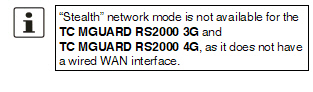
In the case of the TC MGUARD RS2000 3G and TC MGUARD RS2000 4G, the WAN is only available via the mobile network, as a WAN interface is not available. The mobile network function is preset. The devices can only be operated in router mode.
The status of the mobile network connection can be queried via SNMP. SNMP traps are sent in the following cases:
–Incoming text message (mGuardEDSGsmIncomingSMS)
–Incoming call (only up to mGuard firmware Version 8.3)
–Mobile network connection error (ping test) (mGuardEDSGsmNetworkProbe)
You can switch SNMP support on and off under Management >> SNMP.
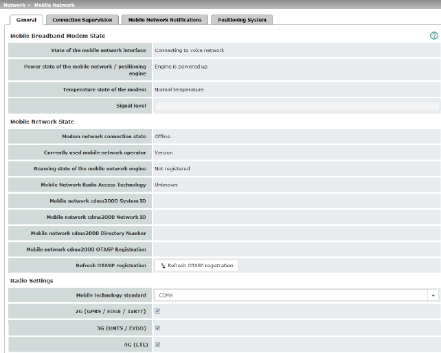
Different status messages are displayed depending on the mobile network standard used (GSM/UMTS/LTE or CDMA).
Display for GSM / UMTS / LTE selection (device-specific)
Display for CDMA selection
|
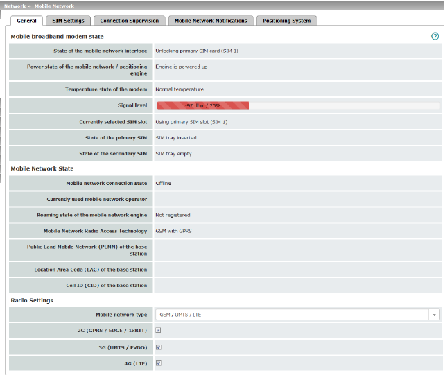
Mobile Broadband Modem State |
State of the mobile network interface |
Indicates the state of the mobile network modem state machine (e.g., dialing into the data network or SIM card error). |
|
|
Power state of the mobile network / positioning engine |
Operating state: Engine is powered up / Engine is powered down |
|
|
Temperature state of the modem |
Temperature state of the mobile network modem In the event that the temperature exceeds or falls below a critical temperature, the mobile network modem switches off automatically. |
|
|
Signal strength |
Strength of the mobile network signal, from The optimum received power is 100% signal strength and - 51 dBm attenuation. |
|
|
Currently selected SIM slot |
Indicates which SIM card slot is used (SIM 1 or SIM 2). |
|
|
State of the primary SIM |
State of the SIM card or SIM tray in slot 1. |
|
|
State of the secondary SIM |
State of the SIM card or SIM tray in slot 2. |
|
Mobile Network State |
Modem network connection state |
Connection state to the mobile data network: Offline / Dialing in / Online |
|
|
Currently used mobile network operator |
Name of the mobile network provider currently used by the mGuard. |
|
|
Roaming state of the mobile network engine |
Possible states: –Registered to home network –Registered to foreign network –Not registered |
|
|
Mobile Network Radio Access Technology |
Mobile network standard currently used |
|
|
Public Land Mobile Network (PLMN) of the base station (Only for "GSM/UMTS/LTE" network connection) |
PLMN: unique identification number of the provider assigned to the base station The PLMN consists of the three-digit Mobile Country Code (MCC) and the two-digit Mobile Network Code (MNC) (MCC + MNC = PLMN). |
|
|
Location Area Code (LAC) of the base station (Only for "GSM/UMTS/LTE" network connection) |
LAC: area code, location in the mobile network (in decimal format) |
|
|
Cell ID (CID) of the base station (Only for "GSM/UMTS/LTE" network connection) |
CID: unique identification number of the mobile phone cell |
|
|
Mobile network cdma2000 System ID (Only for "CDMA" network connection) |
SID: system identification number of the CDMA mobile phone cell |
|
|
Mobile network cdma2000 Network ID (Only for "CDMA" network connection) |
NID: network identification number of the CDMA mobile phone cell |
|
|
Mobile network cdma2000 Directory Number (Only for "CDMA" network connection) |
Phone number (Mobile Directory Number – MDN) assigned to the mGuard by the CDMA network provider (e.g., Verizon). Valid for the North American Numbering Plan (NANP). The number is only displayed once successfully registered with the CDMA network provider (e.g., Verizon OTASP) (see below). |
|
|
Mobile network cdma2000 OTASP Registration (Only for "CDMA" network connection) |
In order that the mGuard can be operated in the mobile network of the CDMA provider (e.g., Verizon), the necessary configurations must be requested and downloaded from the CDMA network provider once. 
mGuard firmware Version 8.3 or earlier: the configuration is downloaded by clicking on the “Verizon registration” button (OTASP method). In order to do this, the mGuard must first be registered with and authorized by Verizon. mGuard firmware Version 8.4 or later: the configuration is downloaded automatically as soon as the mGuard registered with and authorized by Verizon connects to the Verizon network via CDMA for the first time. Following successful registration, the MDN is displayed under "Mobile Directory Number (MDN) or the CDMA cell". |
|
|
Refresh OTASP registration |
If an already registered mGuard device is to be operated with a new mobile phone contract (e. g. data plan from Verizon) and a new mobile phone number, the registration must be repeated. Click on the "Refresh OTASP registration" button to download the new configuration. After successful registration, the new MDN will be displayed under "Mobile network cdma2000 Directory Number". 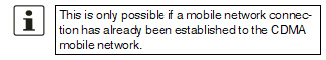
To refresh the registration on the command line, enter the following command: perform_action cdma/otasp_verizon . |
|
Radio Settings |
The explicit selection of mobile network frequencies is no longer necessary or possible from mGuard firmware Version 8.4. It is enough to simply select the mobile network standard. 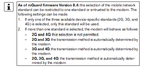
|
|
|
|
Mobile network standard (Device-specific) |
No mobile network connection: mobile network connection disabled GSM / UMTS / LTE: mobile network connection via the SIM card provider CDMA: mobile network connection using the CDMA method without SIM card The MEID code, which is printed on the housing of the device used, is used for registration and authorization with the CDMA provider (e.g., Verizon). The configuration is registered and downloaded automatically with mGuard firmware Version 8.4 or later (see above). |
|
|
2G (GPRS / EDGE / 1xRTT) (Device-specific) |
Depending on the selected mobile network standard, the data is transmitted using GPRS/EDGE (GSM/UMTS/LTE) or 1xRTT (CDMA). |
|
|
3G (UMTS / EVDO) (Device-specific) |
Depending on the selected mobile network standard, the data is transmitted using UMTS (GSM/UMTS/LTE) or EVDO (CDMA). |
|
|
4G (LTE) (Device-specific) |
The data is transmitted using LTE (GSM/UMTS/LTE). |
|
Not displayed when "CDMA" used as mobile network standard. |
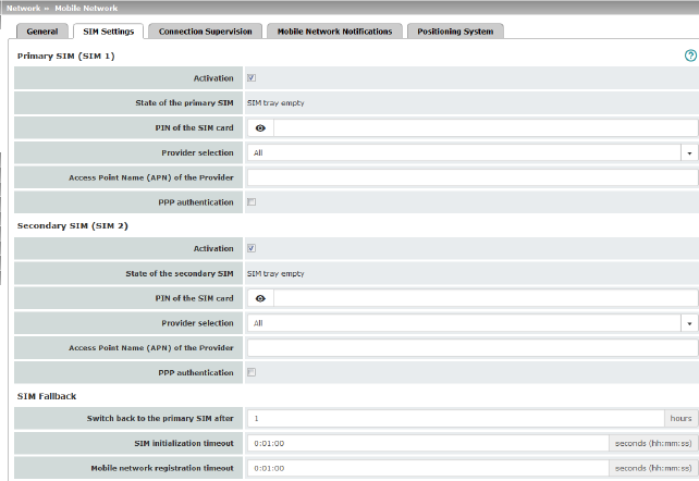
The TC MGUARD RS4000/RS2000 3G and TC MGUARD RS4000/RS2000 4G devices can be equipped with two SIM cards.
The TC MGUARD RS4000/RS2000 4G ATT and VZW devices can only be operated with one SIM card. SIM Fallback is not possible.
If two SIM cards are used, the following applies: The SIM card in slot SIM 1 is the primary SIM card which is normally used to establish the connection. If this connection fails, the device can turn to the secondary SIM card in slot SIM 2. To do this, both SIM cards must be activated and configured. It is also possible to only use the primary or just the secondary SIM card on its own.
The primary SIM card (SIM 1) in slot 1 takes over the mobile network connection in these cases:
–If the mGuard is restarted
–When logging into the mobile network provider again
–In the event of an error in the mobile network connection of SIM 2 (see Connection Supervision)
–If there is a timeout, which is set under "Switch back to the primary SIM after" (see SIM Fallback)
The secondary SIM card (SIM 2) in slot 2 takes over the mobile network connection if the mobile network connection via the primary SIM card (SIM 1) fails. The secondary SIM card (SIM 2) maintains the mobile network connection until one of the aforementioned cases occurs.
|
|
|
|
|
Activation |
You can activate or deactivate the use of the SIM card. |
|
|
|
State of the primary SIM |
The following statuses are displayed: –SIM tray inserted and empty (without SIM card) –No SIM tray (neither the SIM card nor tray are available) –PIN required –SIM card authorized (PIN) –Wrong PIN –PUK required (if the PIN is incorrectly entered too often) –SIM card error |
|
|
PIN of the SIM card |
Numeric code provided by the mobile network provider. This field is left empty for SIM cards without a PIN. |
|
|
Provider selection |
You can restrict the SIM card registration to one provider from the list or allow all providers. When All is selected, a suitable provider that is available is selected automatically. |
|
|
Manual APN selection (Only for TC MGUARD RS4000/RS2000 4G ATT and VZW) |
Default: deactivated The Access Point Name (APN) on the TC MGUARD RS4000/RS2000 4G ATT and VZW devices is automatically transmitted by the provider and applied by the device. If errors occur during automatic transmission, the feature Manual APN selection must be activated and the APN must be entered in the field Access Point Name (APN) of the provider (see below). |
|
|
Access Point Name (APN) of the Provider |
Enter the name of the access gateway for the packet transmission of your mobile network provider. The APN can be obtained from your mobile network provider. |
|
|
APN (Only for TC MGUARD RS4000/RS2000 4G ATT and VZW) |
The APN automatically obtained from the provider or entered manually is displayed. |
|
|
Telephone number (Only for TC MGUARD RS4000/RS2000 4G VZW) |
The telephone number assigned to the SIM card is displayed. |
|
|
OTA registration status (Only for TC MGUARD RS4000/RS2000 4G VZW) |
Status of the registration with the mobile network operator |
|
|
PPP authentication is required by some mobile network providers for the transmission of packet data. If you activate the function, you must also enter the corresponding access data (login and password). |
|
|
|
PPP login (only when “PPP authentication” function is activated) |
Enter the PAP or CHAP user identifier (login) to log into the access gateway of the mobile network provider. This information can be obtained from your mobile network provider. |
|
|
PPP password (only when “PPP authentication” function is activated) |
Enter the PAP or CHAP user password to log into the access gateway of the mobile network provider. This information can be obtained from your mobile network provider. |
|
(Only if both SIM cards are activated) (Not available at TC MGUARD RS4000/RS2000 4G ATT and VZW)
|
Specifies the time in hours (0 - 24) after which the secondary SIM card (SIM 2) switches back to the primary SIM card (SIM 1), provided the check of the targets was successful. In the event of an error, it immediately switches back to the primary SIM card. If “0” is specified as the value, it only switches back to the primary SIM card in the event of an error or after a restart. |
|
|
|
SIM initialization timeout |
Maximum time period for SIM initialization. If this time is exceeded, switches to the other SIM if activated. Otherwise, the activated SIM is initialized again. |
|
|
Mobile network registration timeout |
Maximum period of time between successful SIM initialization and connection with the voice network (text messages can be sent). If this time is exceeded, switches to the other SIM if activated. Otherwise, waits until the mobile network modem can reconnect to the voice network. |
|
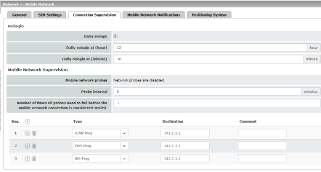
Network >> Mobile Network >> Connection Supervision |
||
|---|---|---|
|
Relogin |
Daily relogin |
The connection to the mobile network provider is disconnected and re-established daily at a fixed time in order to avoid forced disconnection by the provider. |
|
|
Daily relogin at (hour) (minute) (Only when “Daily relogin” function is activated) |
Time at which the connection is renewed. 
Default: 0 h : 0 m Values: 0 - 23 hours and 0 - 59 minutes |
|
Mobile Network Supervision |
You can use the following probe targets to check whether data can actually be transmitted with an active mobile network connection with packet data transmission. To do so, probe targets (hosts) in the Internet are pinged and therefore tested at specific intervals to see whether at least one of the targets can be reached. If the defined targets cannot be reached after specified intervals, the mobile network connection is perceived to be faulty. If two SIM cards are configured, the mobile network connection is re-established with the SIM card that is currently not in use. In the case of only one activated SIM card or in the CDMA process, the mobile network modem is reset and then the mobile network connection is reestablished. Furthermore, state changes in mobile network supervision can be sent by e-mail, text message or SNMP trap. |
|
|
|
Mobile network probes |
Status of network supervision 
|
|
|
Probe interval (minutes) |
Time between two tests in minutes Value: 2 - 60 minutes (default: 5 minutes) |
|
|
Number of times all probes need to fail before the mobile network connection is considered stalled |
Number of attempts before the mobile network connection is considered to be aborted. Value: 1 - 5 (default: 3) |
|
|
Probe targets |
Type: the ping type can be configured separately for each probe target: –ICMP Ping (ICMP echo request, ICMP echo reply): Determines whether a device can be reached at the IP address specified. This is the most common ping test. However, the response to this ping test is disabled on some devices. This means that they do not respond even though they can be reached. –DNS Ping (DNS query to UDP port 53): Determines whether an operational DNS server can be reached at the IP address specified. A generic request is sent to the DNS server with the specified IP address, and every DNS server that can be reached responds to this request. –IKE Ping (IPsec IKE query to UDP port 500): Determines whether a VPN gateway can be reached at the IP address specified. |
|
|
|
Destination: here you can enter the probe targets as host names or IP addresses. The probe targets are processed in the specified order. 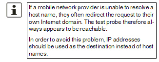
Comment: freely selectable comment. |
6.2.4Mobile Network Notifications
The TC MGUARD RS4000/RS2000 3G and TC MGUARD RS4000/RS2000 4G devices can send and receive text messages.
Text messages can be sent via the following mechanisms:
–Web interface
–Command line
To do so, you must enter the recipient number followed by a space and then add the message:
/Packages/mguard-api_0/mbin/action gsm/sms “<recipient number> <message>”
Text messages can be sent to freely definable mobile network recipients for selectable events. A complete list of all events can be found under "Event table" on page 69.
Incoming text messages can be used to control VPN connections or firewall rule sets, for example (see "Token for text message trigger" on page 271 and 328).
|
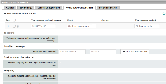
Text Message Notifications |
Any text message recipient can be linked to predefined events and a freely definable message. The list is processed from top to bottom. 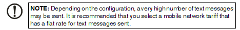
|
|
|
|
Text message recipient number |
Recipient number for the text message |
|
|
Event |
When the selected event occurs, the linked recipient number is selected and the event is sent to them as a text message. A text message can also be stored and sent. A complete list of all events can be found under "Event table" on page 69. |
|
|
Selector (When an appropriate event is selected: OpenVPN Connection Activation state- or IPsec VPN Connection) |
A configured VPN connection can be selected here, which is monitored via text message. |
|
|
Text message content |
Here you can enter the text that is sent as a text message. Maximum of 160 characters from the GSM-based alphabet (see Text Message Character Set) or 70 Unicode symbols. The text is freely definable. You can use blocks from the event table which can be inserted as placeholders in plain text (\A and \V) or in machine-readable format (\a and v\). Time stamps in the form of a placeholder (\T or \t (machine readable)) can also be inserted (see "Event table" on page 69). |
|
Incoming text messages can be used to start or stop VPN connections. The text message must contain a configured token and the corresponding command for the relevant VPN connection. |
||
|
|
Telephone number and content of the last incoming text message |
Displays the sender number and message of the last incoming text message. |
|
Send text message |
Send text message now |
Recipient number Enter the telephone number of the recipient of the text message (maximum 20 digits, and a '+' for international telephone numbers). Message Enter the text that is to be sent as a text message here. Maximum of 160 characters from the GSM-based alphabet (see Text Message Character Set) or 70 Unicode symbols. Send text message now Click on the “Send text message now” button to send the message. |
|
In firmware versions prior to 8.3, the approach was to try and send a maximum number of characters in one text message. Since some telecommunications providers do not adhere to standards, some text messages were not sent accurately (word-for-word). This led to problems in automated applications. In order to ensure word-for-word transmission, the characters used needed to be restricted to the following basic character set: –(space) –0-9 –a - z –A - Z –! " # % & ( ) * + , - / : ; < = > ? |
||
|
|
Restrict outgoing text messages to basic character set |
In order to force the use of the basic character set, activate the function. Once activated, a text message sent by the mGuard is not translated into the language set for the web user interface; it is always sent in English. This does not affect e-mail notifications that are sent. |
|
Outgoing |
Telephone number and content of the last outgoing text message |
Sender number and message of the last text message sent. |
|
|
State of the last outgoing text message |
State of the last text message sent. |
|
Depending on the device, this menu is not available on all mobile devices. |
|
|
|
|
|
Settings |
Enable positioning engine |
When you enable this function, the position of the mGuard is determined. |
|
|
When the function is activated, the local system time is synchronized by means of the positioning system used. If time synchronization by means of NTP server is activated at the same time (see "Enable NTP time synchronization" on page 53), all sources are used to determine the time. |
|
|
Current Position |
Validity of the positional data |
Indicates whether valid position data is available for the mGuard. |
|
|
Number of satellites |
Displays the number of available GPS/GLONASS satellites for the mGuard which are available for position determination. |
|
|
Latitude of the current position |
Displays the current latitude of the mGuard position. |
|
|
Longitude of the current position |
Displays the current longitude of the mGuard position. |
|
|
Show in OpenStreetMap |
A link to OpenStreetMap is generated from the mGuard position data, which can be used with a web browser to display a map view of the current position of the mGuard. |

For all of the devices mentioned above, data traffic is routed via the serial interface and not via the mGuard WAN port when in Modem or Built-in (mobile network) modem network mode and from there it continues as follows.
–A – data traffic is routed via the externally accessible serial interface (serial port) to which an external modem must be connected.
–B – data traffic is routed via the built-in (mobile network) modem/built-in ISDN terminal adapter, if available.
In both cases, the connection to the ISP and therefore the Internet is established via the telephone network using a modem or ISDN terminal adapter.
In Modem network mode, the serial interface of the mGuard is not available for the PPP dial-in option or for configuration purposes (see page "Modem" on page 186).
After selecting Modem1 as the network mode, specify the required parameters for the modem connection on the Dial-out and/or Dial-in tab page (see "Dial-out" on page 177 and "Dial-in" on page 183).
Enter the connection settings for an external modem on the Modem tab page (see "Modem" on page 186).
This is a DTE interface in the case of the serial interface.
|
Only for TC MGUARD RS4000 3G, TC MGUARD RS4000 4G, FL MGUARD RS4000, FL MGUARD RS4004, mGuard Centerport (Innominate), FL MGUARD CENTERPORT, FL MGUARD RS, FL MGUARD BLADE, FL MGUARD DELTA, mGuard delta (Innominate) |
|
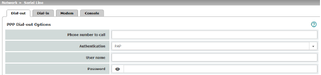
PPP Dial-out Options (Not for TC MGUARD RS2000 3G, TC MGUARD RS2000 4G, FL MGUARD RS2005, FL MGUARD RS2000) |
|
|
|
|
Phone number of the Internet service provider. The connection to the Internet is established after establishing the telephone connection. Command syntax: together with the previously set ATD modem command for dialing, the following dial sequence, for example, is created for the connected modem: ATD765432. A compatible pulse dialing procedure that works in all scenarios is used as standard. Special dial characters can be used in the dial sequence. |
|
|
|
|
HAYES special dial characters –W: instructs the modem to insert a dialing pause at this point until the dial tone can be heard. Used when the modem is connected to a private branch exchange. An outside line must be obtained first for outgoing calls by dialing a specific number (e.g., 0) before the phone number of the relevant subscriber can be dialed. Example: ATD0W765432 –T: switch to tone dialing. Insert the special dial character T before the phone number if the faster tone dialing procedure is to be used (with tone-compatible telephone connections). Example: ATDT765432 |
|
|
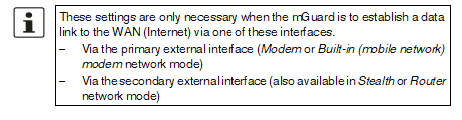
PAP / CHAP / None –PAP = Password Authentication Protocol –CHAP = Challenge Handshake Authentication Protocol These terms describe procedures for the secure transmission of authentication data using the Point-to-Point Protocol. If the Internet service provider requires the user to log in using a user name and password, then PAP or CHAP is used as the authentication method. The user name, password, and any other data that must be specified by the user to establish a connection to the Internet are given to the user by the Internet service provider. The corresponding fields are displayed depending on whether PAP, CHAP or None is selected. Enter the corresponding data in these fields. |
|
|
|
|
|
|
|
User name |
User name specified during Internet service provider login to access the Internet. |
|
|
Password |
Password specified during Internet service provider login to access the Internet. |
|
|
PAP server authentication |
The following two input fields are shown when the function is activated: |
|
|
User name of the server |
User name and password that the mGuard requests from the server. The mGuard only allows the connection if the server returns the agreed user name/password combination. |
|
|
Server password |
|
|
|
See under "If “None” is selected as the authentication method" on page 179. |
|
|
|
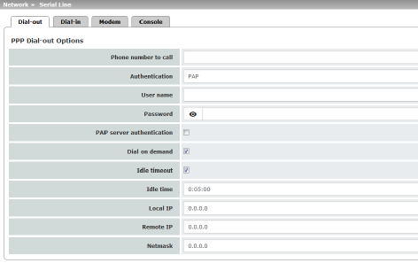
If authentication is via CHAP: 
|
|
|
|
Local name |
A name for the mGuard that it uses to log into the Internet service provider. The service provider may have several customers and it uses this name to identify who is attempting to dial in. After the mGuard has logged into the Internet service provider with this name, the service provider also compares the password specified for client authentication (see below). The connection can only be established successfully if the name is known to the service provider and the password matches. |
|
|
Remote name |
A name given to the mGuard by the Internet service provider for identification purposes. The mGuard will not establish a connection to the service provider if the ISP does not give the correct name. |
|
|
Password for client authentication |
Password that must be specified during Internet service provider login to access the Internet. |
|
|
CHAP server authentication |
The following two input fields are shown when the function is activated: |
|
|
Password that the mGuard requests from the server. The mGuard only allows the connection if the server returns the agreed password. |
|
|
|
See "If “None” is selected as the authentication method" on page 179. |
|
|
|
In this case, the fields that relate to the PAP or CHAP authentication methods are hidden. |
|
|
|
Only the fields that define further settings remain visible below. 
|
|
Other common settings
|
Network >> Interfaces >> Dial-out |
||
|---|---|---|
|
PPP Dial-out Options |
If the function is activated (default): this setting is useful for telephone connections where costs are calculated according to the connection time. The mGuard only commands the modem to establish a telephone connection when network packets are actually to be transferred. It also instructs the modem to terminate the telephone connection as soon as no more network packets are to be transmitted for a specific time (see value in Idle timeout field). By doing this, however, the mGuard is not constantly available externally, i.e., for incoming data packets. |
|
|
|
–Often: the mGuard is configured so that it synchronizes its system time (date and time) regularly with an external NTP server. –Sporadically: the mGuard acts as a DNS server and must perform a DNS request for a client. –After a restart: an active VPN connection is set to Initiate. If this is the case, the mGuard establishes a connection after every restart. –After a restart: for an active VPN connection, the gateway of the peer is specified as the host name. After a restart, the mGuard must request the IP address that corresponds to the host name from a DNS server. –Often: VPN connections are set up and DPD messages are sent regularly (see "Dead Peer Detection" on page 357). –Often: the mGuard is configured to send its external IP address regularly to a DNS service, e.g., DynDNS, so that it can still be accessed via its host name. –Often: the IP addresses of peer VPN gateways must be requested from the DynDNS service or they must be kept up to date by new queries. –Sporadically: the mGuard is configured so that SNMP traps are sent to the remote server. –Sporadically: the mGuard is configured to permit and accept remote access via HTTPS, SSH or SNMP. (The mGuard then sends reply packets to every IP address from which an access attempt is made (if the firewall rules permit this access)). –Often: the mGuard is configured to connect to an HTTPS server at regular intervals in order to download any configuration profiles available there (see "Management >> Central Management" on page 114). |
|
|
|
|
When the function is deactivated, the mGuard establishes a telephone connection using the connected modem as soon as possible after a restart or activation of Modem network mode. This remains permanently in place, regardless of whether or not data is transmitted. If the telephone connection is then interrupted, the mGuard attempts to restore it immediately. Thus a permanent connection is created, like a permanent line. By doing this, the mGuard is constantly available externally, i.e., for incoming data packets. |
|
|
Idle timeout |
Only considered when Dial on demand is activated. When the function is activated (default), the mGuard terminates the telephone connection as soon as no data traffic is transmitted over the time period specified under Idle time. The mGuard gives the connected modem the relevant command for terminating the telephone connection. When the function is deactivated, the mGuard does not give the connected modem a command for terminating the telephone connection. |
|
|
Idle time (seconds) |
Default: 300 seconds (00:05:00) If there is still no data traffic after the time specified here has elapsed, the mGuard can terminate the telephone connection (see above under Idle timeout). The entry can be in seconds [ss], minutes and seconds [mm:ss] or hours, minutes, and seconds [hh:mm:ss]. |
|
|
Local IP |
IP address of the serial interface of the mGuard that now acts as the WAN interface. If this IP address is assigned dynamically by the Internet service provider, use the preset value: 0.0.0.0. Otherwise, e.g., for the assignment of a fixed IP address, enter this here. |
|
|
Remote IP |
IP address of the peer. When connecting to the Internet, this is the IP address of the Internet service provider, which is used to provide access to the Internet. As the Point-to-Point Protocol (PPP) is used for the connection, the IP address does not usually have to be specified. This means you can use the preset value: 0.0.0.0. |
|
|
Netmask |
The netmask specified here belongs to both the Local IP address and the Remote IP address. Normally all three values (Local IP, IP address of peer, Netmask) are either fixed or remain set to 0.0.0.0. Enter the connection settings for an external modem on the Modem tab page (see "Modem" on page 186). |
|
Only for TC MGUARD RS4000 3G, FL MGUARD RS4004, FL MGUARD RS4000, mGuard Centerport (Innominate), FL MGUARD CENTERPORT, FL MGUARD RS, FL MGUARD BLADE, FL MGUARD DELTA, mGuard delta (Innominate) |
|
(Not for TC MGUARD RS2000 3G, TC MGUARD RS2000 4G, FL MGUARD RS2005, FL MGUARD RS2000) |
|
|
|
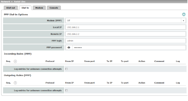
Should only be configured if the mGuard is to permit PPP dial-in via one of the following: –A modem connected to the serial interface –A built-in modem (as option for the FL MGUARD RS) –A built-in mobile network modem (for TC MGUARD RS4000 3G, TC MGUARD RS4000 4G). PPP dial-in can be used to access the LAN (or the mGuard for configuration purposes) (see "Modem" on page 186). If the modem is used for dialing out by acting as the primary external interface (Modem network mode) of the mGuard or as its secondary external interface (when activated in Stealth or Router network mode), it is not available for the PPP dial-in option. |
||
|
|
Modem (PPP) (Only for TC MGUARD RS4000 3G, TC MGUARD RS4000 4G, FL MGUARD RS4000, FL MGUARD RS4004, FL MGUARD RS (without built-in modem/ISDN TA), FL MGUARD DELTA, mGuard delta (Innominate)) |
Off / Internal Modem / External Modem This option must be set to “Off” if no serial interface and no internal modem is to be used for the PPP dial-in option. If this option is set to Internal/External Modem, the PPP dial-in option is available. The connection settings for the connected external modem should be made on the Modem tab page. |
|
|
(Only for FL MGUARD RS (with built-in modem/ISDN TA)) |
Off / Built-in modem / External Modem This option must be set to Off if no serial interface should be used for the PPP dial-in option. If this option is set to External Modem, the PPP dial-in option is available. An external modem must then be connected to the serial interface. The connection settings for the connected external modem should be made on the Modem tab page. If this option is set to Built-in modem, the PPP dial-in option is available. In this case, the modem connection is not established via the serial socket on the front. Instead it is established via the terminal strip on the bottom where the built-in modem or built-in ISDN terminal adapter is connected to the telephone network. The connection settings for the built-in modem should be made on the Modem tab page. If the Built-in modem option is used, the serial interface can also be used. For the options for using the serial interface, see "Modem" on page 186. |
|
|
Local IP |
IP address of the mGuard via which it can be accessed for a PPP connection. |
|
|
Remote IP |
IP address of the peer of the PPP connection. |
|
|
PPP login |
User identifier (login) that must be specified by the PPP peer in order to access the mGuard via a PPP connection. |
|
|
PPP password |
The password that must be specified by the PPP peer in order to access the mGuard via a PPP connection. |
|
Firewall rules for incoming PPP connections to the LAN interface. If multiple firewall rules are defined, these are queried starting from the top of the list of entries until an appropriate rule is found. This rule is then applied. If the list of rules contains further subsequent rules that could also apply, these rules are ignored. The following options are available: |
||
|
Incoming firewall rules (serial interface) |
Protocol |
All means TCP, UDP, ICMP, GRE, and other IP protocols |
|
|
From IP / To IP |
0.0.0.0/0 means all IP addresses. To specify an address area, use CIDR format (see "CIDR (Classless Inter-Domain Routing)" on page 29). |
|
|
From port / To port (Only for TCP and UDP protocols) |
any refers to any port. startport:endport (e.g., 110:120) refers to a port range. Individual ports can be specified using the port number or the corresponding service name (e.g., 110 for pop3 or pop3 for 110). |
|
|
Action |
Accept means that the data packets may pass through. Reject means that the data packets are sent back and the sender is informed of their rejection. Drop means that the data packets are not permitted to pass through. They are discarded, which means that the sender is not informed of their whereabouts. Name of rule sets, if defined. When a rule set is selected, the firewall rules configured under this rule set take effect (see "Rule Records" on page 270). 
Name of Modbus TCP rule sets, if defined. When a Modbus TCP rule set is selected, the firewall rules configured under this rule set take effect (see "Modbus TCP" on page 283). |
|
|
Comment |
Freely selectable comment for this rule. |
|
|
Log |
For each individual firewall rule, you can specify whether the use of the rule: –Should be logged – activate Log function –Should not be logged – deactivate Log function (default) |
|
|
Log entries for unknown connection attempts |
When the function is activated, all connection attempts that are not covered by the rules defined above are logged. |
|
Outgoing Rules (PPP)
|
Firewall rules for outgoing PPP connections from the LAN interface. The parameters correspond to those under Incoming Rules (PPP). These outgoing rules apply to data packets that are sent out via a data link initiated by PPP dial-in. |
|
|
Only for TC MGUARD RS4000 3G, TC MGUARD RS2000 3G (only console), FL MGUARD RS4004, FL MGUARD RS4000/RS2000, mGuard Centerport (Innominate), FL MGUARD CENTERPORT, FL MGUARD RS, FL MGUARD SMART2, FL MGUARD DELTA (not FL MGUARD SMART 533/266, FL MGUARD PCI(E)4000, FL MGUARD BLADE, mGuard delta (Innominate). |
Some mGuard models have a serial interface that can be accessed externally, while the FL MGUARD RS is also available with a built-in modem as an option (see "Network >> Interfaces" on page 131).
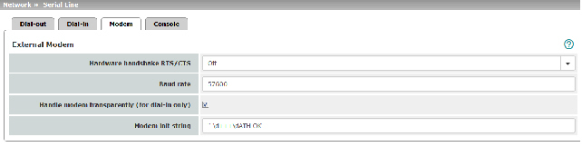
Options for using the serial interface
The serial interface can be used alternatively as follows:
Primary external interface
(This menu item is not included in the scope of functions for the TC MGUARD RS2000 3G, TC MGUARD RS2000 4G, FL MGUARD RS2005 or FL MGUARD RS2000)
As a primary external interface, if the network mode is set to Modem under Network >> Interfaces on the General tab page (see "Network >> Interfaces" on page 131 and "General" on page 137).
In this case, data traffic is not processed via the WAN port (Ethernet interface), but via the serial interface.
Secondary external interface
(This menu item is not included in the scope of functions for the TC MGUARD RS2000 3G, TC MGUARD RS2000 4G, FL MGUARD RS2005 or FL MGUARD RS2000)
As a secondary external interface, if Secondary External Interface is activated and Modem is selected under Network >> Interfaces on the General tab page (see "Network >> Interfaces" on page 131 and "General" on page 137).
In this case, data traffic is processed (permanently or temporarily) via the serial interface.
For dialing in to the LAN or for configuration purposes (This menu item is not included in the scope of functions for the TC MGUARD RS2000 3G, TC MGUARD RS2000 4G, FL MGUARD RS2005 or FL MGUARD RS2000)
Used for dialing in to the LAN or for configuration purposes (see also "Dial-in" on page 183). The following options are available:
–A modem is connected to the serial interface of the mGuard. This modem is connected to the telephone network (fixed-line or GSM network).
(The connection to the telephone network is established via the terminal strip on the bottom of the device for the FL MGUARD RS with built-in modem or ISDN terminal adapter.)
This enables a remote PC that is also connected to the telephone network via a modem or ISDN adapter to establish a PPP (Point-to Point Protocol) dial-up connection to the mGuard.
This method is referred to as a PPP dial-in option. It can be used for access to the LAN, which is located behind the mGuard or for configuration of the mGuard. Dial-in is the interface designation used for this connection type in firewall selection lists.
In order to access the LAN with a Windows computer using the dial-up connection, a network connection must be set up on this computer in which the dial-up connection to the mGuard is defined. In addition, the IP address of the mGuard (or its host name) must be defined as the gateway for this connection so that the connections to the LAN can be routed via this address.
To access the web configuration interface of the mGuard, you must enter the IP address of the mGuard (or its host name) in the address line of the web browser.
–The serial interface of the mGuard is connected to the serial interface of a PC.
On the PC, the connection to the mGuard is established using a terminal program and the configuration is implemented using the command line of the mGuard.
If an external modem is connected to the serial interface, you may have to enter corresponding settings below under External Modem, regardless of the use of the serial interface and the modem connected to it.
|
(Not for TC MGUARD RS2000 3G, TC MGUARD RS2000 4G, FL MGUARD RS2005, FL MGUARD RS2000) |
Hardware handshake RTS/CTS |
Off / On When set to On, flow is controlled by means of RTS and CTS signals for PPP connections. |
|
Baud rate |
Default: 57600 / (FL MGUARD GT/GT: 38400). Transmission speed for communication between the mGuard and modem via the serial connecting cable between both devices. This value should be set to the highest value supported by the modem. If the value is set lower than the maximum possible speed that the modem can reach on the telephone line, the telephone line will not be used to its full potential. |
|
|
|
Handle modem transparently (for dial-in only) |
If the external modem is used for dial-in (see Page 183), activation of the function means that the mGuard does not initialize the modem. The subsequently configured modem initialization sequence is not observed. Thus, either a modem is connected which can answer calls itself (default profile of the modem contains “auto answer”) or a null modem cable to a computer can be used instead of the modem, and the PPP protocol is used over this. |
|
|
Modem init string |
Specifies the initialization sequence that the mGuard sends to the connected modem. Default: '' \d+++\dATH OK Consult the modem user manual for the initialization sequence for this modem. |
|
|
|
The initialization sequence is a sequence of character strings expected by the modem and commands that are then sent to the modem so that the modem can establish a connection. |
The preset initialization sequence has the following meaning:
|
’’ (two simple quotation marks placed directly after one another) |
The empty character string inside the quotation marks means that the mGuard does not initially expect any information from the connected modem, but instead sends the following text directly to the modem. |
|
\d+++\dATH |
The mGuard sends this character string to the modem in order to determine whether the modem is ready to accept commands. |
|
OK |
Specifies that the mGuard expects the OK character string from the modem as a response to \d+++\dATH. |
|
On many modem models it is possible to save modem default settings to the modem itself. However, this option should not be used. Initialization sequences should be configured externally instead (i.e., on the mGuard). In the event of a modem fault, the modem can then be replaced quickly and smoothly without changing the modem default settings. |
|
If the external modem is to be used for incoming calls without the modem default settings being entered accordingly, then you have to inform the modem that it should accept incoming calls after it rings. If using the extended HAYES command set, append the character string “ AT&S0=1 OK” (a space followed by “AT&S0=1”, followed by a space, followed by “OK”) to the initialization sequence. |
|
Depending on their default settings, some external modems require a physical connection to the DTR cable of the serial interface in order to operate correctly. Because the mGuard models do not provide this cable at the external serial interface, the character string “ AT&D0 OK” (a space followed by “AT&D0”, followed by a space, followed by “OK”) must be appended to the above initialization sequence. According to the extended HAYES command set, this sequence means that the modem does not use the DTR cable. |
|
If the external modem is to be used for outgoing calls, it is connected to a private branch exchange, and if this private branch exchange does not generate a dial tone after the connection is opened, then the modem must be instructed not to wait for a dial tone before dialing. In this case, append the character string “ ATX3 OK” (a space followed by “ATX3”, followed by a space, followed by “OK”) to the initialization sequence. In order to wait for the dial tone, the control character “W” should be inserted in the Phone number to call after the digit for dialing an outside line. |
For the FL MGUARD RS with built-in modem/built-in ISDN modem (ISDN terminal adapter)
The FL MGUARD RS is available with a built-in analog modem/built-in ISDN terminal adapter as an option. The built-in modem or built-in ISDN terminal adapter can be used as follows:
Primary External Interface
–As a primary external interface, if the network mode is set to Built-in modem under Network >> Interfaces on the General tab page (see "Network >> Interfaces" on page 131 and "General" on page 137). In this case, data traffic is not processed via the WAN port (Ethernet interface), but via this modem.
Secondary External Interface
–As a secondary external interface, if Secondary External Interface is activated and Built-in modem is selected under Network >> Interfaces on the General tab page (see "Network >> Interfaces" on page 131 and "General" on page 137). In this case, data traffic is also processed via the serial interface.
PPP Dial-in Options
–For the PPP dial-in option (see "Options for using the serial interface" on page 186).
Please note that the serial interface of the device also provides similar options for use (see above). Therefore on an FL MGUARD RS with a built-in modem, normal data traffic can be routed via a modem connection (Modem network mode) and a second modem connection can be used simultaneously for the PPP dial-in option, for example.
For the FL MGUARD RS with built-in modem
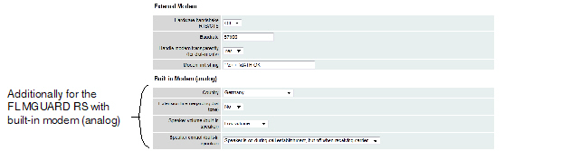
|
Network >> Interfaces >> Modem / Console (for the FL MGUARD RS with built-in modem) |
||
|---|---|---|
|
External Modem |
As for the TC MGUARD RS4000 3G, TC MGUARD RS4000 4G, FL MGUARD RS4004, FL MGUARD RS (without built-in modem), FL MGUARD DELTA, mGuard Centerport (Innominate), FL MGUARD CENTERPORT, FL MGUARD BLADE, mGuard delta (Innominate): Configuration as above for External Modem (see "External Modem" on page 187). |
|
|
Built-in Modem (analog) |
Country |
The country where the mGuard with built-in modem is operated must be specified here. This ensures that the built-in modem operates according to the applicable remote access guidelines in the respective country and that it recognizes and uses dial tones correctly, for example. |
|
|
When set to No, the mGuard waits for the dial tone when the telephone network is accessed and the mGuard is calling the peer. When set to Yes, the mGuard does not wait for a dial tone. Instead it begins dialing the peer immediately. This procedure may be necessary if the built-in modem of the mGuard is connected to a private branch exchange that does not emit a dial tone when it is “picked up”. When a specific number must be dialed to access an outside line, e.g., “0”, this number should be added to the start of the desired peer phone number that is to be dialed. |
|
|
|
||
|
|
|
|
|
|
Speaker control (built-in speaker) |
These two settings specify which sounds should be emitted by the mGuard speaker and at what volume. |
For the FL MGUARD RS with built-in ISDN terminal adapter
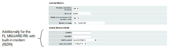
|
Network >> Interfaces >> Modem / Console (for the FL MGUARD RS with ISDN terminal adapter) |
||
|---|---|---|
|
External Modem |
As for the FL MGUARD RS4000, TC MGUARD RS4000 3G, TC MGUARD RS4000 4G, FL MGUARD RS4004, FL MGUARD RS (without built-in modem), mGuard Centerport (Innominate), FL MGUARD CENTERPORT, FL MGUARD BLADE, mGuard delta (Innominate): Configuration as above for External Modem (see "External Modem" on page 187). |
|
|
Built-in Modem (ISDN) |
1st MSN |
For outgoing calls, the mGuard transmits the MSN (Multiple Subscriber Number) entered here to the called peer. In addition, the mGuard can receive incoming calls via this MSN (provided dial-in operation is enabled, see General tab page). Maximum of 25 alphanumeric characters; the following special characters can be used: *, #, : (colon) |
|
|
If the mGuard should also receive incoming calls via another number for dial-in operation (if enabled), enter the second MSN here. |
|
|
|
ISDN protocol |
The EuroISDN protocol (also known as NET3) is used in Germany and many other European countries. Otherwise the ISDN protocol should be specified according to the country. If necessary, this must be requested from the relevant phone company. |
|
|
Layer-2 protocol |
The set of rules used by the ISDN terminal adapter of the local mGuard to communicate with its ISDN peer. This generally is the ISDN modem of the Internet service provider used to establish the connection to the Internet. It must be requested from the Internet service provider. PPP/ML-PPP is often used. |
|
Only for TC MGUARD RS4000 3G, TC MGUARD RS2000 3G (only console), FL MGUARD RS4004, FL MGUARD RS4000/RS2000, mGuard Centerport (Innominate), FL MGUARD CENTERPORT, FL MGUARD RS, FL MGUARD SMART2, FL MGUARD DELTA (not FL MGUARD SMART 533/266, FL MGUARD PCI(E)4000, FL MGUARD BLADE, mGuard delta (Innominate). |
|
Network >> Serial interface >> Console |
||
|---|---|---|
|
||
|
|
Baud rate |
9600 / 19200 / 38400 / 57600 (default) / 115200 (Default for FL MGUARD GT/GT: 38400) The transmission speed of the serial interface is specified via the selection list. |
|
|
Off / On When set to On, flow is controlled by means of RTS and CTS signals. |
|
|
|
(Only FL MGUARD SMART2) |
When the function is deactivated, the FL MGUARD SMART2 uses the USB connection solely as a power supply. When the function is activated, the FL MGUARD SMART2 provides an additional serial interface for the connected computer through the USB interface. The serial interface can be accessed on the computer using a terminal program. The FL MGUARD SMART2 provides a console through the serial interface, which can then be used in the terminal program. A special driver is required under Windows in order to use the serial console via USB. This can be downloaded directly from the mGuard. |
|
|
Serial USB driver (Windows) (Only FL MGUARD SMART2) |
Click on the “Download Windows Driver from device” button to download the Windows driver. |
|
COM Server (Only for mGuard platforms with serial interface) |
The mGuard platforms with a serial interface have an integrated COM server as of firmware 8.0. This enables serial interface data exchange via an IP connection. Three options are available. –RFC 2217 (Telnet server, complies with RFC 2217). In this mode, the serial interface can be configured via client software in the network. The Telnet server is available via the port which is defined under "Local port" . –RAW client In this mode, the mGuard initiates a connection to the address which is set under "IP address of the peer" . The connection is established via the port which is configured under "Remote port" . The interface can be configured here ("Serial parameters" ). The settings of the serial console are used for the baud rate and the hardware handshake (see "External Modem" under "Network >> Serial interface >> Modem" ). –RAW server Behaves in the same way as the RAW client. However, the RAW server responds to incoming connections via the port which is configured under "Local port" . |
|
|
|
Type |
Here you can select the way that the COM server should operate. Possible options are: RFC 2217, RAW client, RAW server. |
|
|
(only for RAW client type) |
Default: 10.1.0.254 Defines the IP address of the peer. |
|
|
(only for RFC 2217 and RAW server type) |
Default: 3001 Defines the port that the COM server should respond to. Values: 1 - 65535. |
|
|
(only for RAW client type) |
Default: 3001 Defines the port to which the RAW client sends the data. Values: 1 - 65535. |
|
|
Via VPN (only for RAW client type) |
The COM servers request is, where possible, carried out via a VPN tunnel. When the function is activated, communication with the server is always via an encrypted VPN tunnel if a suitable one is available. If the function is deactivated or if no suitable VPN tunnel is available, the traffic is sent unencrypted via the default gateway. 
|
|
|
Defines the parity and stop bits for the serial interface. Supported packet lengths of the serial interface: 8 Bit / 7 Bit. –8 Bits (7 Bits), 1 stop bit, no parity (standard with 8 Bit) –8 Bits (7 Bits), 1 stop bit, even parity –8 Bits (7 Bits), 1 stop bit, odd parity –8 Bits (7 Bits), 2 stop bits, no parity –8 Bits (7 Bits), 2 stop bits, even parity –8 Bits (7 Bits), 2 stop bits, odd parity |
|
|
COM Server Allowed Networks |
Access rules can be defined for the COM server to prevent unauthorized access to it. The default rule does not allow any access via the external interface. |
|
|
|
From IP |
0.0.0.0/0 means all IP addresses. To specify an address area, use CIDR format (see "CIDR (Classless Inter-Domain Routing)" on page 29). |
|
|
Interfaces |
Internal / External / External 2 / DMZ / VPN / GRE / Dial-in Interface for which the rule should apply. |
|
|
Action |
Accept means that the data packets may pass through. Reject means that the data packets are sent back. The sender is informed of their rejection. Drop means that the data packets are not permitted to pass through. The sender is not informed of their whereabouts. |
|
|
Comment |
Freely selectable comment for this rule. |
|
|
Log |
For each firewall rule you can specify whether the event is to be logged if the rule is applied. |
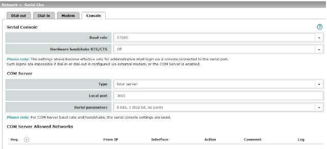
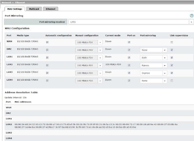
|
(Only for TC MGUARD RS4000 3G, TC MGUARD RS4000 4G, FL MGUARD RS4004) |
Port mirroring receiver |
The integrated switch controls port mirroring in order to monitor the network traffic. Here, you can decide which ports you want to monitor. The switch then sends copies of data packets from the monitored ports to a selected port. The port mirroring function enables any packets to be forwarded to a specific recipient. You can select the receiver port or the mirroring of the incoming and outgoing packets from each switch port. |
|
MAU Configuration (Not for TC MGUARD RS2000 3G, TC MGUARD RS2000 4G) |
Configuration and status indication of the Ethernet connections: |
|
|
|
Name of the Ethernet connection to which the row refers. |
|
|
|
Media type of the Ethernet connection. |
|
|
|
Activated: tries to determine the required operating mode automatically. Deactivated: uses the operating mode specified in the “Manual configuration” column. |
|
|
|
Manual configuration |
The desired operating mode when Automatic configuration is deactivated. |
|
|
Current mode |
The current operating mode of the network connection. |
|
|
Port on |
Switches the Ethernet connection on or off. The Port on function is not supported by the mGuard Centerport (Innominate) or FL MGUARD CENTERPORT. The Port on function is supported with restrictions on: mGuard delta (Innominate): the internal side (switch ports) cannot be switched off. FL MGUARD PCI 533/266: in driver mode, the internal network interface cannot be switched off (however, this is possible in Power-over-PCI mode). |
|
|
Only visible when the "Management >> Service I/O >> Alarm output" menu item under Management >> Service I/O >> Alarm output is set to “Supervise”. If link supervision is active, the alarm output is opened if one link does not indicate connectivity. |
|
|
|
Port mirroring |
The port mirroring function enables any packets to be forwarded to a specific recipient. You can select the receiver port or the mirroring of the incoming and outgoing packets from each switch port. |
|
Address Resolution Table (Only for TC MGUARD RS4000 3G, TC MGUARD RS4000 4G, FL MGUARD RS4004) |
Port |
Name of the Ethernet connection to which the row refers. |
|
MAC addresses |
Lists the MAC addresses of the connected Ethernet-capable devices. The switch can learn MAC addresses which belong to the ports of its connected Ethernet-capable devices. The contents of the list can be deleted by clicking on the “Purge” button. |
|
|
Port Statistics (Only for TC MGUARD RS4000 3G, TC MGUARD RS4000 4G, FL MGUARD RS4004) |
A statistic is displayed for each physically accessible port of the integrated Managed Switch. The counter can be reset via the web interface or the following command: /Packages/mguard-api_0/mbin/action switch/reset-phy-counters |
|
|
|
Port |
Name of the Ethernet connection to which the row refers. |
|
|
TX collisions |
Number of errors while sending the data |
|
|
TX octets |
Data volume sent |
|
|
Number of received frames with invalid checksum |
|
|
|
RX good octets |
Volume of the valid data received |
|
Only available with the TC MGUARD RS4000 3G, TC MGUARD RS4000 4G, FL MGUARD RS4004. |
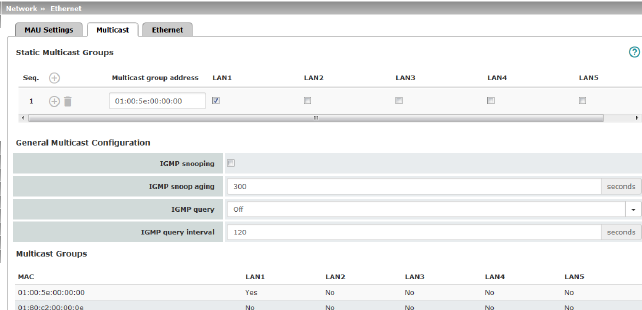
|
Network >> Ethernet >> Multicast |
||
|---|---|---|
|
Static Multicast Groups |
Static Multicast Groups |
Multicast is a technology which enables data to be sent to a group of recipients, without the transmitter having to send it multiple times. The data replication takes place through the distributor within the network. You can create a list of multicast group addresses. The data is forwarded to the configured ports (LAN1 ... LAN5). |
|
General Multicast Configuration |
IGMP snooping |
The switch uses IGMP snooping to guarantee that multicast data is only forwarded via ports which are intended for this use. |
|
|
IGMP snoop aging |
Period, after which membership to the multicast group expires, in seconds. |
|
|
IGMP query |
IGMP is used to join and leave a multicast group. Here, the IGMP version can be selected (Version v3 is not supported). |
|
|
IGMP query interval |
Interval in which IGMP queries are generated in seconds |
|
Multicast Groups |
Displays the multicast groups. The display contains all static entries and the dynamic entries which are discovered by IGMP snooping. |
|
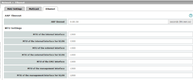
|
Network >> Ethernet >> Ethernet |
||
|---|---|---|
|
ARP Timeout |
ARP Timeout |
Service life of entries in the ARP table. The entry can be in seconds [ss], minutes and seconds [mm:ss] or hours, minutes, and seconds [hh:mm:ss]. MAC and IP addresses are assigned to each other in the ARP table. |
|
The MTU settings |
MTU of the ... interface |
The maximum transfer unit (MTU) defines the maximum IP packet length that may be used for the relevant interface. The following applies for a VLAN interface: 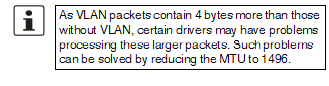
|
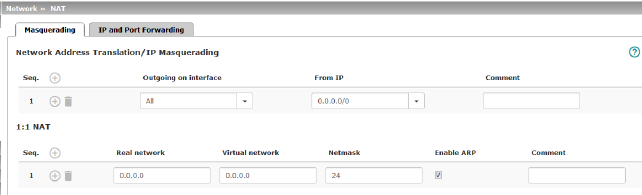
|
Network >> NAT >> Masquerading |
||
|---|---|---|
|
Lists the rules established for NAT (Network Address Translation). For outgoing data packets, the device can rewrite the specified sender IP addresses from its internal network to its own external address, a technique referred to as NAT (Network Address Translation), see also NAT (Network Address Translation) in the glossary. This method is used if the internal addresses cannot or should not be routed externally, e.g., because a private address area such as 192.168.x.x or the internal network structure should be hidden. The method can also be used to hide external network structures from the internal devices. To do so, set the Internal option under Outgoing on interface. The Internal setting allows for communication between two separate IP networks where the IP devices have not configured a (useful) default route or differentiated routing settings (e.g., PLCs without the corresponding settings). The corresponding settings must be made under 1:1 NAT. This method is also referred to as IP masquerading. |
||
|
|
Default setting: NAT is not active. 


|
|
|
|
Internal / External / External 2 / DMZ / Any External1 Specifies via which interface the data packets are sent so that the rule applies to them. Any External refers to the External and External 2 interfaces. |
|
|
|
|
Masquerading is defined, which applies for network data flows in Router mode. These data flows are initiated so that they lead to a destination device which can be accessed over the selected network interface on the mGuard. |
|
|
|
To do this, the mGuard replaces the IP address of the initiator with a suitable IP address of the selected network interface in all associated data packets. The effect is the same as for the other values of the same variables. The IP address of the initiator is hidden from the destination of the data flow. In particular, the destination does not require any routes in order to respond in a data flow of this type (not even a default route (default gateway)). |
|
|
|
|
|
|
From IP |
0.0.0.0/0 means that all internal IP addresses are subject to the NAT procedure. To specify an address area, use CIDR format (see "CIDR (Classless Inter-Domain Routing)" on page 29). Name of IP groups, if defined. When a name is specified for an IP group, the host names, IP addresses, IP areas or networks saved under this name are taken into consideration (see "IP/Port Groups" on page 276). 
|
|
|
Can be filled with appropriate comments. |
|
|
|
Lists the rules established for 1:1 NAT (Network Address Translation). With 1:1 NAT, the sender IP addresses are exchanged so that each individual address is exchanged with another specific address, and is not exchanged with the same address for all data packets, as in IP masquerading. This enables the mGuard to mirror addresses from the real network to the virtual network. |
|
|
Example: |
The mGuard is connected to network 192.168.0.0/24 via its LAN port and to network 10.0.0.0/24 via its WAN port. By using 1:1 NAT, the LAN computer with IP address 192.168.0.8 can be accessed via IP address 10.0.0.8 in the virtual network. 
|
|
|
|
The mGuard claims the IP addresses entered for the “Virtual network” for the devices in its “Real network”. The mGuard returns ARP answers for all addresses from the specified “Virtual network” on behalf of the devices in the “Real network”. The IP addresses entered under “Virtual network” must not be used. They must not be assigned to other devices or used in any way, as an IP address conflict would otherwise occur in the virtual network. This even applies when no device exists in the “Real network” for one or more IP addresses from the specified “Virtual network”. |
|
|
|
Default setting: 1:1 NAT is not active. 

|
|
|
|
Real network |
The real IP address of the client that should be reachable from another network via the virtual IP address (depending on the scenario at LAN, WAN, or DMZ port). One or more clients can be reachable depending on the network mask. From mGuard firmware 8.0.0, 1:1-NAT between all interfaces is possible (LAN <–> WAN, LAN <–> DMZ, DMZ <–> WAN). |
|
|
Virtual network |
The virtual IP address with which the clients are reachable from the other network (depending on the scenario at LAN, WAN, or DMZ port). 
From mGuard firmware 8.0.0, 1:1-NAT between all interfaces is possible (LAN <–> WAN, LAN <–> DMZ, DMZ <–> WAN). |
|
|
Netmask |
The netmask as a value between 1 and 32 for the local and external network address (see also "CIDR (Classless Inter-Domain Routing)" on page 29). |
|
|
Enable ARP |
When the function is activated, ARP requests sent to the virtual network are answered on behalf of the mGuard. This means that hosts located in the real network can be accessed via their virtual address. When the function is deactivated, ARP requests sent to the virtual network remain unanswered. This means that hosts in the real network cannot be accessed. |
|
|
Comment |
Can be filled with appropriate comments. |
|
1External 2 and Any External are only for devices with a serial interface: TC MGUARD RS4000/RS2000 3G, TC MGUARD RS4000/RS2000 4G, FL MGUARD RS4004/RS2005, FL MGUARD RS4000/RS2000, mGuard Centerport (Innominate), FL MGUARD CENTERPORT, FL MGUARD RS, FL MGUARD BLADE, FL MGUARD DELTA, mGuard delta (Innominate) (see "Secondary External Interface" on page 152). |
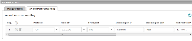
|
Lists the rules defined for port forwarding (DNAT = Destination NAT). IP and port forwarding performs the following: the headers of incoming data packets from the external network, which are addressed to the external IP address (or one of the external IP addresses) of the mGuard and to a specific port of the mGuard, are rewritten in order to forward them to a specific computer in the internal network and to a specific port on this computer. In other words, the IP address and port number in the header of incoming data packets are changed. IP and port forwarding from the internal network behaves as described above. 

|
||
|
|
Specify the protocol to which the rule should apply. GRE GRE protocol IP packets can be forwarded. However, only one GRE connection is supported at any given time. If more than one device sends GRE packets to the same external IP address, the mGuard may not be able to feed back reply packets correctly. We recommend only forwarding GRE packets from specific transmitters. These could be ones that have had a forwarding rule set up for their source address by entering the transmitter address in the “From IP” field, e.g., 193.194.195.196/32. |
|
|
|
From IP |
The sender address for forwarding. 0.0.0.0/0 means all addresses. To specify an address area, use CIDR format (see "CIDR (Classless Inter-Domain Routing)" on page 29). Name of IP groups, if defined. When a name is specified for an IP group, the host names, IP addresses, IP areas or networks saved under this name are taken into consideration (see "IP/Port Groups" on page 276). 
|
|
|
From port |
The sender port for forwarding. any refers to any port. Either the port number or the corresponding service name can be specified here, e.g., pop3 for port 110 or http for port 80. Name of port groups, if defined. When a name is specified for a port group, the ports or port ranges saved under this name are taken into consideration (see "IP/Port Groups" on page 276). |
|
|
Incoming on IP |
–Specify the external IP address (or one of the external IP addresses) of the mGuard here, or –Specify the internal IP address (or one of the internal IP addresses) of the mGuard here, or –Use the variable %extern (if the external IP address of the mGuard is changed dynamically so that the external IP address cannot be specified). If multiple static IP addresses are used for the WAN port, the %extern variable always refers to the first IP address in the list. |
|
|
Incoming on port |
The original destination port specified in the incoming data packets. Either the port number or the corresponding service name can be specified here, e.g., pop3 for port 110 or http for port 80. This information is not relevant for the “GRE” protocol. It is ignored by the mGuard. |
|
|
Redirect to IP |
The internal IP address to which the data packets should be forwarded and into which the original destination addresses are translated. |
|
|
Redirect to port |
The port to which the data packets should be forwarded and into which the original port data is translated. Either the port number or the corresponding service name can be specified here, e.g., pop3 for port 110 or http for port 80. This information is not relevant for the “GRE” protocol. It is ignored by the mGuard. |
|
|
Comment |
Freely selectable comment for this rule. |
|
|
Log |
For each individual port forwarding rule, you can specify whether the use of the rule: –Should be logged – activate Log function –Should not be logged – deactivate Log function (default) |
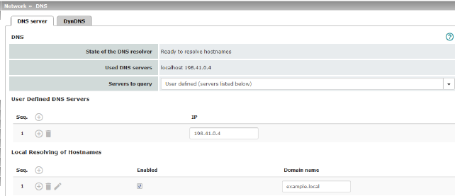
|
Network >> DNS >> DNS server |
||
|---|---|---|
|
DNS |
If the mGuard is to initiate a connection to a peer on its own (e.g., to a VPN gateway or NTP server) and it is specified in the form of a host name (i.e., www.example.com), the mGuard must determine which IP address belongs to the host name. To do this, it connects to a domain name server (DNS) to query the corresponding IP address there. The IP address determined for the host name is stored in the cache so that it can be found directly (i.e., more quickly) for other host name resolutions. With the Local resolving of hostnames function, the mGuard can also be configured to respond to DNS requests for locally used host names itself by accessing an internal, previously configured directory. The locally connected clients can be configured (manually or via DHCP) so that the local address of the mGuard is used as the address of the DNS server to be used. If the mGuard is operated in Stealth mode, the management IP address of the mGuard (if this is configured) must be used for the clients, or the IP address 1.1.1.1 must be entered as the local address of the mGuard. |
|
|
|
DNS cache state |
Status of the host name resolution |
|
|
Used DNS servers |
DNS servers for which the associated IP address was queried. |
|
|
DNS root servers Requests are sent to the root name servers on the Internet whose IP addresses are stored on the mGuard. These addresses rarely change. Provider-defined (i.e., via PPPoE or DHCP) The DNS servers of the Internet service provider (ISP) that provide access to the Internet are used. Only select this setting if the mGuard operates in PPPoE, PPTP, Modem mode or in Router mode with DHCP. From mGuard firmware version 8.6.0, the setting can also be used if the mGuard is located in Stealth mode (automatic). In this case, the DNS server that the client uses can be recognized and taken on. User-defined (servers listed below) If this setting is selected, the mGuard will connect to the DNS servers listed under User-defined DNS servers. |
|
|
User-defined DNS servers (Only when user-defined is selected as root server) |
The IP addresses of DNS servers can be entered in this list. If this should be used by the mGuard, select the "User-defined (servers listed below)" option under Servers to query. |
|
|
You can configure multiple entries with assignment pairs of host names and IP addresses for various domain names. You have the option to define, change (edit), and delete assignment pairs of host names and IP addresses. You can also activate or deactivate the resolution of host names for a domain. In addition, you can delete a domain with all its assignment pairs. |
||
|
|
Creating a table with assignment pairs for a domain: •Open a new row and click on the Changing or deleting assignment pairs belonging to a domain: •Click on the After clicking on Edit row, the DNS Records tab page is displayed: 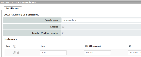
|
|
|
|
Domain for the hosts |
The name can be freely assigned, but it must adhere to the rules for assigning domain names. It is assigned to every host name. |
|
|
Active |
Activates or deactivates the Local Resolving of Hostnames function for the domain specified in the “Domain name” field. |
|
|
Deactivated: the mGuard only resolves host names, i.e., it supplies the assigned IP address for host names. Activated: as with “Deactivated”. It is also possible to determine the host names assigned to an IP address. |
|
|
|
Hostnames |
The table can have any number of entries. 
|
|
|
Host |
Host name |
|
|
TTL (hh:mm:ss) |
Abbreviation for Time To Live. Default: 3600 seconds (1:00:00) Specifies how long called assignment pairs may be stored in the cache of the calling computer. |
|
|
IP |
The IP address assigned to the host name in this table row. |
Example: Local Resolving of Hostnames
The “Local Resolving of Hostnames” function is used in the following scenario, for example:
A plant operates a number of identically structured machines, each one as a cell. The local networks of cells A, B, and C are each connected to the plant network via the Internet using the mGuard. Each cell contains multiple control elements, which can be addressed via their IP addresses. Different address areas are used for each cell.
A service technician should be able to use her/his notebook on site to connect to the local network for machine A, B or C and to communicate with the individual controllers. So that the technician does not have to know and enter the IP address for every single controller in machine A, B or C, host names are assigned to the IP addresses of the controllers in accordance with a standardized diagram that the service technician uses. The host names used for machines A, B, and C are identical, i.e., the controller for the packing machine in all three machines has the host name “pack”, for example. However, each machine is assigned an individual domain name, e.g., cell-a.example.com.
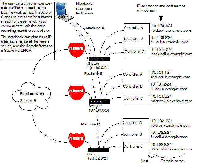
Figure 6-1: Local Resolving of Hostnames
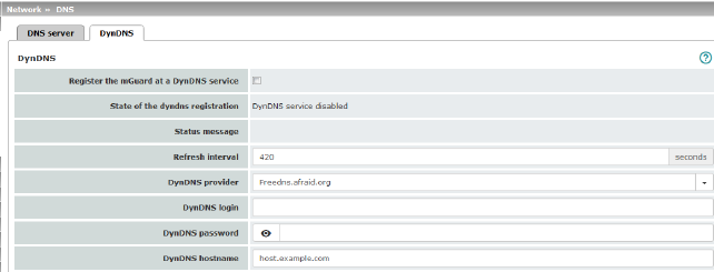
|
Network >> DNS >> DynDNS |
||
|---|---|---|
|
DynDNS |
In order for a VPN connection to be established, at least one partner IP address must be known so that the partners can contact each other. This condition is not met if both participants are assigned IP addresses dynamically by their respective Internet service providers. In this case, a DynDNS service such as DynDNS.org or DNS4BIZ.com can be of assistance. With a DynDNS service, the currently valid IP address is registered under a fixed name. If you have registered with one of the DynDNS services supported by the mGuard, you can enter the corresponding information in this dialog box. When using the TC MGUARD RS4000/RS2000 3G and TC MGUARD RS4000/RS2000 4G, be aware that DynDNS is not permitted by all mobile network providers. |
|
|
|
Register the mGuard at a DynDNS service |
Activate the function if you have registered with a DynDNS provider and if the mGuard is to use this service. The mGuard then reports its current IP address to the DynDNS service (i.e., the one assigned for its Internet connection by the Internet service provider). |
|
|
Refresh Interval (sec) |
Default: 420 (seconds). The mGuard informs the DynDNS service of its new IP address whenever the IP address of its Internet connection is changed. In addition, the device can also report its IP address at the interval specified here. This setting has no effect for some DynDNS providers, such as DynDNS.org, as too many updates can cause the account to be closed. |
|
|
The providers in this list support the same protocol as the mGuard. Select the name of the provider with whom you are registered, e.g., DynDNS.org, TinyDynDNS, DNS4BIZ. If your provider is not in the list, select DynDNS-compatible and enter the server and port for this provider. |
|
|
|
Only visible when DynDNS provider is set to DynDNS-compatible. Name of the server for the DynDNS provider. |
|
|
|
DynDNS port |
Only visible when DynDNS provider is set to DynDNS-compatible. Number of the port for the DynDNS provider. |
|
|
DynDNS |
Enter the user identifier assigned by the DynDNS provider here. |
|
|
DynDNS password |
Enter the password assigned by the DynDNS provider here. |
|
|
DynDNS hostname |
The host name selected for this mGuard at the DynDNS service, providing you use a DynDNS service and have entered the corresponding data above. The mGuard can then be accessed via this host name. |
The dynamic host configuration protocol (DHCP) can be used to automatically assign the network configuration set here to the computers connected directly to the mGuard. You can specify the DHCP settings for the internal interface (LAN port) under Internal DHCP and the DHCP settings for the external interface (WAN port) under External DHCP. DHCP settings for the DMZ interface (DMZ port) can be made under DMZ DHCP.
The External DHCP and DMZ DHCP menu items are not included in the scope of functions of FL MGUARD RS2000, TC MGUARD RS2000 3G, TC MGUARD RS2000 4G and FL MGUARD RS2005.
|
The DHCP server also operates in Stealth mode. In multi-stealth mode, the external DHCP server of the mGuard cannot be used if a VLAN ID is assigned as the management IP. |
|
IP configuration for Windows computers: when you start the DHCP server of the mGuard, you can configure the locally connected computers so that they obtain their IP addresses automatically from the mGuard via DHCP. |
Under Windows XP
•In the Start menu, select “Control Panel, Network Connections”.
•Right-click on the LAN adapter icon and select “Properties” from the context menu.
•On the “General” tab, select “Internet Protocol (TCP/IP)” under “This connection uses the following items”, then click on the “Properties” button.
•Make the appropriate entries and settings in the “Internet Protocol Properties (TCP/IP)” dialog box.
Under Windows 7
•In the Start menu, select: “Control Panel >> Network and Internet >> Network and Sharing Center”.
•Click on “Local Area Connection” under “Connections:”.
•Click on the “Properties” button in the “Local Area Connection Status” window (administrator rights required).
•In the “Local Area Connection Properties” window, select “Internet Protocol Version 4 (TCP/IPv4)” and click on the “Properties” button.
•Make the appropriate entries and settings in the “Internet Protocol Version 4 (TCP/IPv4) Properties” dialog box.
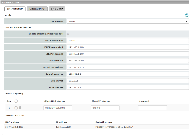
|
Network >> DHCP >> Internal DHCP |
||
|---|---|---|
|
|
The settings for Internal DHCP and External DHCP are essentially identical and are not described separately in this section. |
|
|
Mode |
Disabled / Server / Relay Set this option to Server if the mGuard is to operate as an independent DHCP server. The corresponding setting options are then displayed below on the tab page (see "DHCP mode: Server" ). Set this option to Relay if the mGuard is to forward DHCP requests to another DHCP server. The corresponding setting options are then displayed below on the tab page (see "DHCP mode: Relay" ). 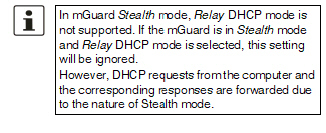
If this option is set to Disabled, the mGuard does not answer any DHCP requests. |
|
|
|
If DHCP mode is set to Server, the corresponding setting options are displayed below as follows. 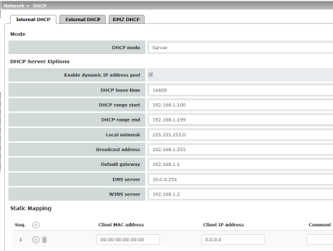
|
|
|
DHCP Server Options |
Enable dynamic IP address pool: |
When the function is activated, the IP address pool specified under DHCP range start and DHCP range end is used (see below). Deactivate the function if only static assignments should be made using the MAC addresses (see below). |
|
|
Time in seconds for which the network configuration assigned to the computer is valid. The client should renew its assigned configuration shortly before this time expires. Otherwise it may be assigned to other computers. |
|
|
|
DHCP range start (With enabled dynamic IP address pool) |
The start of the address area from which the DHCP server of the mGuard should assign IP addresses to locally connected computers. |
|
|
DHCP range end (With enabled dynamic IP address pool) |
The end of the address area from which the DHCP server of the mGuard should assign IP addresses to locally connected computers. |
|
|
Local netmask |
Specifies the netmask of the computers. Default: 255.255.255.0 |
|
|
Broadcast address |
Specifies the broadcast address of the computers. |
|
|
Specifies which IP address should be used by the computer as the default gateway. Usually this is the internal IP address of the mGuard. |
|
|
|
DNS server |
Address of the server used by the computer to resolve host names in IP addresses via the Domain Name Service (DNS). If the DNS service of the mGuard is to be used, enter the internal IP address of the mGuard here. |
|
|
WINS server |
Address of the server used by the computer to resolve host names in addresses via the Windows Internet Naming Service (WINS). |
|
Static Mapping |
Client MAC address |
To find out the MAC address of your computer, proceed as follows: Windows 95/98/ME: •Start winipcfg in a DOS box. Windows NT/2000/XP/: •Start ipconfig /all in a command prompt. The MAC address is displayed as the “Physical Address”. Linux: •Call /sbin/ifconfig or ip link show in a shell. |
|
|
|
The following options are available: –Client/computer MAC address (without spaces or hyphens) –Client IP address |
|
|
Client IP address |
The static IP address of the computer to be assigned to the MAC address. 


|
|
Current Leases |
The current leases assigned by the DHCP server are displayed with MAC address, IP address, and expiration date (timeout). |
|
|
|
If DHCP mode is set to Relay, the corresponding setting options are displayed below as follows. 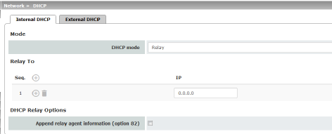
|
|
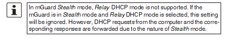
|
||
|
|
DHCP servers to relay to |
A list of one or more DHCP servers to which DHCP requests should be forwarded. |
|
|
Append relay agent information (option 82) |
When forwarding, additional information for the DHCP servers to which information is being forwarded can be appended according to RFC 3046. |
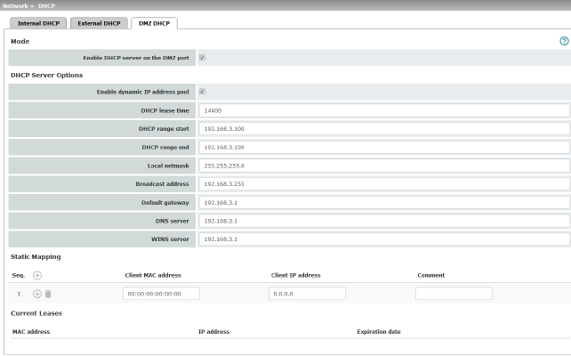
From mGuard firmware version 8.6.0, the DHCP server functionality of the mGuard is expanded on its DMZ interface (DMZ port). The mGuard can automatically assign a network configuration to clients connected to the DMZ port via the DHCP protocol.
|
Network >> DHCP >> DMZ DHCP |
||
|---|---|---|
|
Mode |
Enable DHCP server on the DMZ port |
Enables the DHCP server on the DMZ interface. If the function is disabled, the mGuard does not answer any DHCP queries on the DMZ interface. |
|
DHCP Server Options |
Enable dynamic IP address pool: |
When the function is activated, the IP address pool specified under DHCP range start and DHCP range end is used (see below). Deactivate the function if only static assignments should be made using the MAC addresses (see below). |
|
|
DHCP lease time |
Time in seconds for which the network configuration assigned to the computer is valid. The client should renew its assigned configuration shortly before this time expires. Otherwise it may be assigned to other computers. |
|
|
DHCP range start (With enabled dynamic IP address pool) |
The start of the address area from which the DHCP server of the mGuard should assign IP addresses to locally connected computers. |
|
|
DHCP range end (With enabled dynamic IP address pool) |
The end of the address area from which the DHCP server of the mGuard should assign IP addresses to locally connected computers. |
|
|
Local netmask |
Specifies the netmask of the computers. Default: 255.255.255.0 |
|
|
Broadcast address |
Specifies the broadcast address of the computers. |
|
|
Default gateway |
Specifies which IP address should be used by the computer as the default gateway. Usually this is the internal IP address of the mGuard. |
|
|
DNS server |
Address of the server used by the computer to resolve host names in IP addresses via the Domain Name Service (DNS). If the DNS service of the mGuard is to be used, enter the internal IP address of the mGuard here. |
|
|
WINS server |
Address of the server used by the computer to resolve host names in addresses via the Windows Internet Naming Service (WINS). |
|
Static Mapping |
Client MAC address |
To find out the MAC address of your computer, proceed as follows: Windows 95/98/ME: •Start winipcfg in a DOS box. Windows NT/2000/XP/: •Start ipconfig /all in a command prompt. The MAC address is displayed as the “Physical Address”. Linux: •Call /sbin/ifconfig or ip link show in a shell. |
|
|
|
The following options are available: –Client/computer MAC address (without spaces or hyphens) –Client IP address |
|
|
Client IP address |
The static IP address of the computer to be assigned to the MAC address. 


|
|
Current Leases |
The current leases assigned by the DHCP server are displayed with MAC address, IP address, and expiration date (timeout). |
|
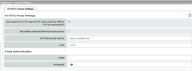
A proxy server can be specified here for the following activities performed by the mGuard itself:
–CRL download
–Firmware update
–Regular configuration profile retrieval from a central location
–Restoring of licenses
|
Network >> Proxy Settings >> HTTP(S) Proxy Settings |
||
|---|---|---|
|
The http(s) proxy settings |
Use proxy for HTTP and HTTPS |
When the function is activated, connections that use the HTTP or HTTPS protocol are transmitted via a proxy server whose address and port should also be specified. Connections that are transmitted in encapsulated form using the VPN in TCP encapsulation function are also routed via the proxy server (see "TCP encapsulation" on page 315). |
|
|
Secondary external interface uses proxy |
Only activate the function if the connection (HTTP or HTTPS) of the secondary external interface is also to be established via a proxy server (see "Secondary External Interface" on page 152). |
|
|
HTTP(S) proxy server |
Host name or IP address of the proxy server. |
|
|
Number of the port to be used, e.g., 3128. |
|
|
Proxy Authentication |
Login |
User identifier (login) for proxy server login. |
|
|
Password |
Password for proxy server login. |
In larger company networks, the use of dynamic routing protocols can make it easier for the network administrator to create and manage routes or even eliminate the need for this.
The OSPF (Open Shortest Path First) routing protocol allows participating routers to exchange and adapt the routes for transmitting IP packets in their autonomous network in real time (dynamically). The best route to each subnetwork is determined for all participating routers and entered in routing tables for the devices. Changes in the network topology are automatically sent to neighboring OSPF routers and eventually distributed by them to all participating OSPF routers.
|
This menu is only available when the mGuard is in “Router” network mode. An OSPF area cannot be assigned to the WAN interface in “DHCP” router mode. |
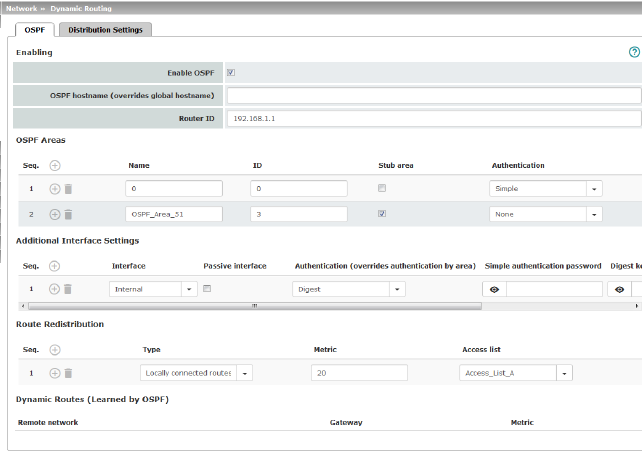
OSPF can be configured for internal, external, and DMZ interfaces. If OSPF is to be used in IPsec connections, the OSPF packets (multicast) must be encapsulated in a GRE tunnel (unicast).
Multiple OSPF areas can be configured in order to distribute local routes and learn external routes. The status of all learned routes is displayed in a table.
|
Network >> Dynamic Routing >> OSPF |
||
|---|---|---|
|
Activation |
Enable OSPF |
When the function is deactivated (default): OSPF is disabled on the device. When the function is activated: dynamic routing using the OSPF protocol is enabled on the device. New routes are learned and distributed by neighboring OSPF routers. 
|
|
|
OSPF hostname |
If an OSPF hostname is assigned here, this is communicated to the participating OSPF routers instead of the global host name. |
|
|
Router ID |
The Router ID in the form of an IP address must be unique within the autonomous system. It can otherwise be freely selected and typically corresponds to the IP address of the WAN or LAN interface of the mGuard. |
|
OSPF Areas |
The autonomous system is segmented using OSPF Areas. The routes between OSPF routers are exchanged within an area. The mGuard can belong to one or more OSPF areas. Distribution between neighboring areas is also possible using the “Transition Area” (see below). |
|
|
|
Name |
The Name can be freely selected (default: ID). An OSPF router is clearly identified by its ID. |
|
|
ID |
In general, the ID can be freely selected. If an OSPF area is assigned the ID 0, it becomes the “Transition Area”. This area is used to exchange routing information between two neighboring areas and then distribute it. |
|
|
Stub area |
If the OSPF area is a stub area, activate the function. |
|
|
Authentication |
None / Simple / Digest Authentication of the mGuard within the OSPF area can be performed using the “Simple” or “Digest” method. The corresponding passwords and digest keys are assigned for the allocated interfaces (see "Additional Interface Settings" ). |
|
Interface |
Internal / External / DMZ Selects the interface for which the settings apply. If no settings are made here, the default settings apply (i.e., OSPF is enabled for the interface and the passwords are not assigned). |
|
|
|
Passive interface |
Default: deactivated When the function is deactivated, OSPF routes are learned and distributed by the interface. When the function is activated, no routes are learned or distributed. |
|
|
Authentication |
None / Digest If Digest is selected, “Digest” is always used for authentication at the selected interface – regardless of the authentication method already assigned to an OSPF area. The authentication method (None / Simple / Digest) that has already been assigned to an OSPF area is therefore ignored and not used. |
|
|
Simple authentication password |
Password for authentication of the OSPF router (for “Simple” authentication method) |
|
|
Digest key |
Digest key for authentication of the OSPF router (for “Digest” authentication method) |
|
|
Digest key ID |
Digest key ID for authentication of the OSPF router (for “Digest” authentication method) (1–255) |
|
Route Redistribution |
Statically entered routes in the kernel routing table can also be distributed using OSPF. Rules can be created for locally connected networks and networks that are reachable via a gateway. The networks whose routes are to be distributed using OSPF can be specified in “access lists” via the "Distribution Settings" . 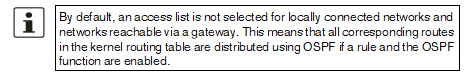
|
|
|
|
Type |
Locally connected routes / Remotely connected routes Locally connected routes: all local networks are distributed using OSPF, if OSPF is enabled. Distribution can be restricted by using access lists. Remotely connected routes: all external networks are distributed using OSPF. External networks include, for example, static as well as IPsec, OpenVPN, and GRE remote networks. Distribution can be restricted by using access lists. |
|
|
Metric |
Metric used to distribute the routes. Unit representing the quality of a connection when a specific route is used (depends on the bandwidth, hop count, costs, and MTU). |
|
|
Access list |
Distributes the routes according to the selected access list (see "Distribution Settings" ). If None is selected, all routes of the selected type are distributed. |
|
Dynamic Routes (learned by OSPF) |
The status of all routes learned using OSPF is displayed. |
|
|
|
Remote network |
Dynamically learned remote network. |
|
|
Gateway |
Gateway to reach the remote network. |
|
|
Metric |
Metric for the learned route. |
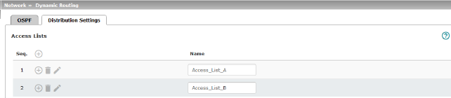
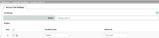
Dynamic routes are automatically distributed using the OSPF protocol. For statically entered routes in the kernel routing table, it must be specified whether they should also be distributed using OSPF.
|
If a rule is selected for either the “Locally connected routes” or “Remotely connected routes” type, by default (Access List = None) all corresponding routes are distributed using OSPF if OSPF is enabled. |
Rules can be created via Distribution Settings which determine the routes that are not learned dynamically that should be distributed using OSPF. These include:
–Locally configured networks (see "Network >> Interfaces" on page 131)
–Static routes entered as external, internal or DMZ networks (see "Network >> Interfaces" on page 131)
–Routes entered in the kernel routing table via OpenVPN (see "OpenVPN Client >> Connections" on page 363)
–Routes entered in the kernel routing table via the GRE tunnel configuration (see "Network >> GRE Tunnel" on page 224)
|
Network >> Dynamic Routing >> Distribution Settings >> Edit >> Access List Settings |
||
|---|---|---|
|
Name |
The Name must be unique and must not be assigned more than once. |
|
|
Rules |
Permit/Deny |
Lists the access list rules. These apply for routes that are not distributed dynamically using OSPF. Permit (standard)means that the route to the entered network is distributed using OSPF. Deny means that the route to the entered network is not distributed using OSPF. |
|
|
Network |
Network whose distribution is permitted or denied by rules. |
Generic Routing Encapsulation (GRE) is a network protocol that is used to encapsulate other protocols (including the OSPF routing protocol) and to transport them in a GRE tunnel via unicast IP connections. OSPF routes can also be learned and distributed via IPsec VPN connections.
To ensure that GRE packets are routed through a secure IPsec tunnel, a preconfigured IPsec connection can be selected for each GRE tunnel.
|
The use of GRE tunnels via IPsec connections of the "Transport" connection type is not possible. |
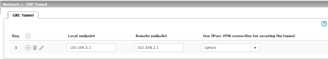
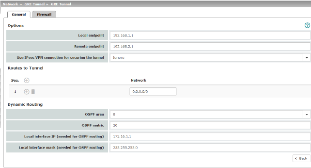
|
Options |
|
|
|
|
Local endpoint |
Local IP address from which the tunnel will be created. The IP address must already be configured under "Network >> Interfaces" for the mGuard itself. |
|
|
Remote endpoint |
Remote IP address to which the tunnel will be created. The IP address must also be configured at the peer. |
|
|
Use IPsec VPN connection for securing the tunnel |
For the selected IPsec connection, it is checked whether the GRE tunnel is routed through and therefore protected by this connection, i.e., whether both endpoints are in the IPsec networks (local and remote). |
|
Routes to Tunnel |
Network |
All peer networks that are to be reached via the GRE tunnel in encapsulated form are entered here. Several routes can be configured for each GRE tunnel. 0.0.0.0/0 means all IP addresses. To specify an address area, use CIDR format (see "CIDR (Classless Inter-Domain Routing)" on page 29). |
|
Dynamic Routing |
OSPF area |
Links the virtual GRE interface to an OSPF area (see "Network >> Dynamic Routing" on page 220). |
|
|
OSPF metric |
Unit representing the quality of a connection through the GRE tunnel. |
|
|
Local interface IP |
IP address of the virtual GRE interface (required in order to exchange routing information between OSPF routers). An IP address in the same network must be configured at the peer for the GRE interface. |
|
|
Local interface mask |
Netmask of the virtual GRE interface. |
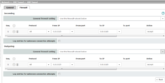
Incoming/Outgoing firewall
While the settings made in the Network Security menu only relate to non-VPN connections and non-GRE connections (see "Network Security menu" on page 259), the settings here only relate to the GRE connection defined on these tab pages.
If multiple GRE connections have been defined, you can restrict the outgoing or incoming access individually for each connection. Any attempts to bypass these restrictions can be logged.
|
By default, the GRE firewall is set to allow all connections for the GRE connection. However, the extended firewall settings defined and explained above apply independently for each individual GRE connection (see "Network Security menu" on page 259, "Network Security >> Packet Filter" on page 259, and "Advanced" on page 278). |
|
If multiple firewall rules are defined, these are queried starting from the top of the list of entries until an appropriate rule is found. This rule is then applied. If the list of rules contains further subsequent rules that could also apply, these rules are ignored. |
|
Network >> GRE Tunnel >> Edit >> Firewall |
||
|---|---|---|
|
Incoming |
General firewall setting |
Accept all incoming connections: the data packets of all incoming connections are allowed. Drop all incoming connections: the data packets of all incoming connections are discarded. Accept Ping only: the data packets of all incoming connections are discarded, except for ping packets (ICMP). Use the firewall ruleset below: displays further setting options. |
|
|
The following settings are only visible if “Use the firewall ruleset below” is set. |
|
|
|
Protocol |
All means TCP, UDP, ICMP, GRE, and other IP protocols. |
|
|
From IP / To IP |
0.0.0.0/0 means all IP addresses. To specify an address area, use CIDR format (see "CIDR (Classless Inter-Domain Routing)" on page 29). Name of IP groups, if defined. When a name is specified for an IP group, the host names, IP addresses, IP areas or networks saved under this name are taken into consideration (see "IP/Port Groups" on page 276). 

Incoming: –From IP: IP address in the GRE tunnel –To IP: 1:1 NAT address or the actual address Outgoing: –From IP: 1:1 NAT address or the actual address –To IP: IP address in the GRE tunnel |
|
|
From port / To port (Only for TCP and UDP protocols) |
any refers to any port. startport:endport (e.g., 110:120) refers to a port range. Individual ports can be specified using the port number or the corresponding service name (e.g., 110 for pop3 or pop3 for 110). Name of port groups, if defined. When a name is specified for a port group, the ports or port ranges saved under this name are taken into consideration (see "IP/Port Groups" on page 276). |
|
|
Action |
Accept means that the data packets may pass through. Reject means that the data packets are sent back and the sender is informed of their rejection. Drop means that the data packets are not permitted to pass through. They are discarded, which means that the sender is not informed of their whereabouts. Name of rule sets, if defined. When a name is specified for rule sets, the firewall rules configured under this name take effect (see "Rule Records" on page 270). 

Name of Modbus TCP rule sets, if defined. When a Modbus TCP rule set is selected, the firewall rules configured under this rule set take effect (see "Modbus TCP" on page 283). |
|
|
Freely selectable comment for this rule. |
|
|
|
Log |
For each individual firewall rule, you can specify whether the use of the rule: –Should be logged – activate Log function –Should not be logged – deactivate Log function (default setting) |
|
|
Log entries for unknown connection attempts |
When the function is activated, all connection attempts that are not covered by the rules defined above are logged. |
|
Outgoing |
The explanation provided under “Incoming” also applies to “Outgoing”. |
|
1 In the case of the FL MGUARD RS with built-in modem or ISDN terminal adapter, Built-in modem is available as an option and in the case of the TC MGUARD RS4000/RS2000 3G and TC MGUARD RS4000/RS2000 4G, Built-in mobile network modem is available as an option