4Management menu
|

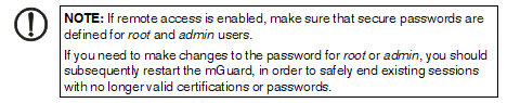
For security reasons, we recommend you change the default root and administrator passwords during initial configuration (see "Authentication >> Administrative Users" on page 155). A message informing you of this will continue to be displayed at the top of the page until the passwords are changed.
|
4.1Management >> System Settings
4.1.1Host
|
Management >> System Settings >> Host
|
|
System
|
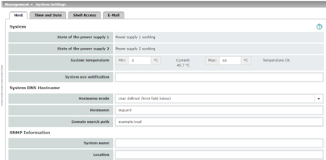
Status of the Power supply 1/2
|
State of both power supply units (model-dependent with redundant power supply)
|
|
|
System temperature (°C)
|
An SNMP trap is triggered if the temperature exceeds or falls below the specified temperature range.
|
|
|
System use notification
|
Freely selectable text for a system use notification that is displayed before logging on at the mGuard device (maximum 1024 characters). Is displayed for:
–Login per SSH login
–Login via the web interface (web UI).
The (repeated) display of the message can be disabled by the customer using a suitable SSH.
Default setting:
The usage of this mGuard security appliance is reserved to authorized staff only. Any intrusion and its attempt without permission is illegal and strictly prohibited.
|
|
System DNS Hostname
|
Hostname mode
|
You can assign a name to the mGuard using the Hostname mode and Hostname fields. This name is then displayed, for example, when logging in via SSH (see "Management >> System Settings" on page 37, "Shell Access" on page 45). Assigning names simplifies the administration of multiple mGuard devices.
User defined (from field below)
(Default) The name entered in the Hostname field is the name used for the mGuard.
If the mGuard is running in Stealth mode, the “User defined” option must be selected under “Hostname mode”.
Provider defined (e.g., via DHCP)
If the selected network mode permits external setting of the host name, e.g., via DHCP, the name supplied by the provider is assigned to the mGuard.
|
|
|
Hostname
|
If the “User defined” option is selected under Hostname mode, enter the name that should be assigned to the mGuard here.
|
|
|
Domain search path
|
This option makes it easier for the user to enter a domain name. If the user enters the domain name in an abbreviated form, the mGuard completes the entry by appending the domain suffix that is defined here under “Domain search path”.
|
|
SNMP Information
|
System name
|
A name that can be freely assigned to the mGuard for administration purposes, e.g., “Hermes”, “Pluto”. (Under SNMP: sysName)
|
|
|
Location
|
A description of the installation location that can be freely assigned, e.g., “Hall IV, Corridor 3”, “Control cabinet”. (Under SNMP: sysLocation)
|
|
|
Contact
|
The name of the contact person responsible for the mGuard, ideally including the phone number. (Under SNMP: sysContact)
|
4.1.2Time and Date
|
Management >> System Settings >> Time and Date
|
|
Time and Date
|
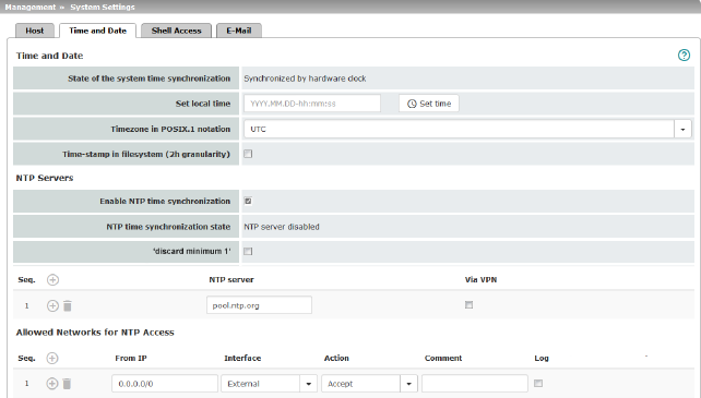
You can set the mGuard system time manually and assign the appropriate time zone or synchronize the system time using the NTP server of your choice.
Connected devices can use the mGuard as an NTP server.
Please note, that for security reasons the NTP version NTP v1 is not supported by the mGuard.
|
|
|
State of the system time
|
Indicates whether the mGuard system time has ever been synchronized with a valid time during mGuard runtime.
Devices without built-in clock always start in “Not synchronized” mode. Devices with a built-in clock usually start in “Synchronized by hardware clock” mode.
The state of the clock only returns to “Not synchronized” if the firmware is reinstalled on the device or if the built-in clock has been disconnected from the power for too long.
Power supply of the built-in clock is ensured by the following components. The rechargeable battery lasts at least five days.
|
|
|
Time-controlled activities
–Time-controlled pick-up of configuration from a configuration server:
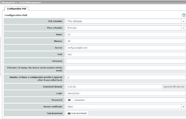
This is the case when the Time schedule setting is selected under the Management >> Central Management, Configuration Pull menu item for the Pull schedule setting (see "Management >> Configuration Profiles" on page 79, "Configuration Pull" on page 96).
–Acceptance of certificates when the system time has not yet been synchronized:
This is the case when the Wait for synchronization of the system time setting is selected under the Authentication >> Certificates, Certificate Settings menu item for the Check the validity period of certificates and CRLs option (see Authentication >> Certificates and "Certificate Settings" on page 170).
|
|
|
The system time can be set or synchronized by various events:
–Synchronized by hardware clock: the mGuard has a built-in clock which has been synchronized with the current time at least once. The display shows whether the clock is synchronized. A synchronized built-in clock ensures that the mGuard has a synchronized system time even after a restart.
–Synchronized manually: the administrator has defined the current time for the mGuard runtime by making a corresponding entry in the Set local time field.
–Synchronized by file system time-stamp: the administrator has set the Time-stamp in filesystem setting to Yes, and has either transmitted the current system time to the mGuard via NTP (see below under NTP Servers) or has entered it under Set local time. The system time of the mGuard is then synchronized using the time stamp after a restart (even if it has no built-in clock). The time might be set exactly again afterwards via NTP.
–Synchronized by Network Time Protocol NTP: the administrator has activated NTP time synchronization under NTP Servers, has entered the address of at least one NTP server, and the mGuard has established a connection with at least one of the specified NTP servers. If the network is working correctly, this occurs a few seconds after a restart. The display in the NTP time synchronization state field may only change to “Synchronized” much later (see the explanation below under NTP time synchronization state).
|
|
|
Set local time
|
Here you can set the time for the mGuard, if no NTP server has been set up or the NTP server cannot be reached.
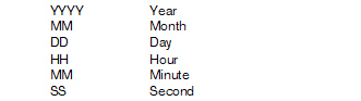
The date and time are specified in the format YYYY.MM.DD-HH:MM:SS:
|
|
|
Timezone in POSIX.1 notation
|
If a current local time (that differs from Greenwich Mean Time) is to be displayed as the current system time, you must enter the number of hours that your local time is ahead of or behind Greenwich Mean Time.
You can select your location from the drop-down list (daylight savings time is usually automatically taken into consideration).
Alternatively, you can set it manually as follows:
Example: in Berlin, the time is one hour ahead of GMT. Therefore, enter: CET-1.
In New York, the time is five hours behind Greenwich Mean Time. Therefore, enter: CET+5.
The only important thing is the -1, -2 or +1, etc. value as only these values are evaluated – not the preceding letters. They can be “CET” or any other designation, such as “UTC”.
If you wish to display Central European Time (e.g., for Germany) and have it automatically switch to/from daylight savings time, enter: CET-1CEST,M3.5.0,M10.5.0/3
|
|
|
Time-stamp in filesystem
|
If this function is activated, the mGuard writes the current system time to its memory every two hours.
If the mGuard is switched off and then on again, a time from this two-hour time slot is displayed, not a time on January 1, 2000.
|
|
NTP Servers
|
The mGuard can act as the NTP server for external computers (NTP = Network Time Protocol). In this case, the computers should be configured so that the address of the mGuard is specified as the NTP server address.
By default, the NTP server of the mGuard device is disabled. After starting the NTP server, access is possible via the internal interface (LAN interface). Firewall rules can be used to enable or restrict access via all available interfaces.
If the mGuard is operated in Stealth mode, the management IP address of the mGuard (if this is configured) must be used for the computers, or the IP address 1.1.1.1 must be entered as the local address of the mGuard.
For the mGuard to act as the NTP server, it must obtain the current date and the current time from an NTP server (= time server). To do this, the address of at least one NTP server must be specified. This feature must also be activated.
|
|
|
Enable NTP time synchronization
|
If this function is activated, the mGuard obtains the date and time from one or more time server(s) and synchronizes itself with it or them.
Initial time synchronization can take up to 15 minutes. During this time, the mGuard continuously compares the time data of the external time server and that of its own time so that this can be adjusted as accurately as possible. Only then can the mGuard act as the NTP server for the computers connected to its LAN interface and provide them with the system time.
After initial time synchronization, the mGuard regularly compares the battery buffered system time with the time servers. Fine adjustment of the time is usually only made in the second range.
|
|
|
NTP time synchronization state
|
Displays the current NTP status.
Shows whether the NTP server running on the mGuard has been synchronized with the configured NTP servers to a sufficient degree of accuracy.
If the system clock of the mGuard has never been synchronized prior to activation of NTP time synchronization, then synchronization can take up to 15 minutes. The NTP server still changes the mGuard system clock to the current time after a few seconds, as soon as it has successfully contacted one of the configured NTP servers. The system time of the mGuard is then regarded as synchronized. Fine adjustment of the time is usually only made in the second range.
|
|
|
‘discard minimum 1‘
|
Enabling this option can improve time synchronization with some NTP clients, especially PLC systems.
Additionally, the refresh interval on the PLC system should be increased to the maximum possible value (e.g. 86400 seconds).
|
|
|
NTP server
|
Enter one or more time servers from which the mGuard should obtain the current time. If several time servers are specified, the mGuard will automatically connect to all of them to determine the current time.
|
|
|
Via VPN
|
The NTP server's request is, where possible, carried out via a VPN tunnel.
When the function is activated, communication with the server is always via an encrypted VPN tunnel if a suitable one is available.
|
|
Allowed Networks for NTP access
(when “Enable NTP time synchronization” function is activated)
|
When the Enable NTP time synchronization function is activated, external devices can access the NTP server of the mGuard. By default, it can only be accessed via the internal interface (LAN interface).
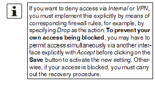
If no rules are set or if no rule applies, the following default settings apply:
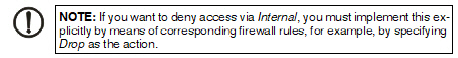
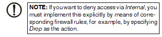
–NTP access via Internal is permitted.
–NTP access via External, DMZ and VPN is denied.
Specify the monitoring options according to your requirements.
The table lists the firewall rules that have been set up. These apply for incoming data packets of an NTP access attempt. If multiple firewall rules are defined, these are queried starting from the top of the list of entries until an appropriate rule is found. This rule is then applied. If the list of rules contains further subsequent rules that could also apply, these rules are ignored.
|
|
|
From IP
|
Enter the address of the computer or network from which access is permitted or forbidden in this field.
The following options are available:
–An IP address.
–To specify an address area, use CIDR format (see "CIDR (Classless Inter-Domain Routing)" on page 34).
–0.0.0.0/0 means all addresses.
|
|
|
Interface
|
Internal / External / DMZ / VPN
Specifies to which interface the rule should apply.
If no rules are set or if no rule applies, the following default settings apply:
–NTP access via Internal is permitted.
–NTP access via External, DMZ and VPN is denied.
Specify the monitoring options according to your requirements.
|
|
|
Action
|
Accept means that the data packets may pass through.
Reject means that the data packets are sent back and the sender is informed of their rejection. (In Stealth mode, Reject has the same effect as Drop.)
Drop means that the data packets are not permitted to pass through. They are discarded, which means that the sender is not informed of their whereabouts.
|
|
|
Comment
|
Freely selectable comment for this rule.
|
|
|
Log
|
For each individual firewall rule, you can specify whether the use of the rule:
–Should be logged – activate Log function
–Should not be logged – deactivate Log function (default)
|
4.1.3Shell Access
|

The mGuard must not be simultaneously configured via web access, shell access or SNMP. Simultaneous configuration via the different access methods might lead to unexpected results.
|
|
Management >> System Settings >> Shell Access
|
|
Shell Access
|
You can configure the mGuard via the web interface or via the command line (shell). Access to the command line is via SSH.
When SSH remote access is activated, the mGuard can be configured from remote computers using the command line. SSH remote access is deactivated by default. It can be activated and restricted to selected networks.
|
|
|
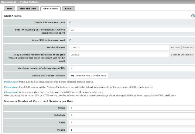
Enable SSH remote access
|
Activate the function to enable SSH remote access.
The firewall rules for the available interfaces must be defined accordingly in order to specify differentiated access options on the mGuard (see "Allowed Networks" on page 49).
|
|
|
Enable SSH access as user root
|
Standard: enabled
If the function is activated, the user "root" can log onto the device via SSH access.
|
|
|
Port for incoming SSH connections (remote administration only)
(Only if SSH remote access is activated)
|
Default: 22
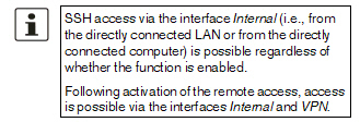
If this port number is changed, the new port number only applies for access via the External, DMZ, and VPN interface.
Port number 22 still applies for internal access.
The remote peer that implements remote access may have to specify the port number defined here during login.
Example:
If this mGuard can be accessed over the Internet via address 123.124.125.21 and default port number 22 has been specified for remote access, you may not need to enter this port number in the SSH client (e.g., PuTTY or OpenSSH) of the remote peer.
If a different port number has been set (e.g., 2222), this must be specified, e.g.: ssh -p 2222 123.124.125.21
|
|
|
Session timeout
|
Specifies after what period of inactivity (in hh:mm:ss) the session is automatically terminated, i.e., automatic logout. When set to 0 (default setting), the session is not terminated automatically.
The effect of the “Session timeout” setting is temporarily suspended if the processing of a shell command exceeds the number of seconds set.
In contrast, the connection can also be aborted if it is no longer able to function correctly, see "Delay between requests for a sign of life" on page 48.
|
|
|
Delay between requests for a sign of life
|
Default: 120 seconds (00:02:00)
Values from 0 seconds to 1 hour can be set. Positive values indicate that the mGuard is sending a request to the peer within the encrypted SSH connection to find out whether it can still be accessed. This request is sent if no activity was detected from the peer for the specified number of seconds (e.g., due to network traffic within the encrypted connection).
The value 0 means that no requests for a sign of life are sent.
The value entered here relates to the functionality of the encrypted SSH connection. As long as it is working properly, the SSH connection is not terminated by the mGuard as a result of this setting, even when the user does not perform any actions during this time.
As the number of simultaneously open sessions is limited (see "Maximum number of concurrent sessions per role" on page 49), it is important to terminate sessions that have expired.
Therefore, the request for a sign of life is preset to 120 seconds. If a maximum of three requests for a sign of life are issued, this causes an expired session to be detected and removed after six minutes. In previous versions, the preset was “0”.
If it is important not to generate additional traffic, you can adjust the value. When “0” is set in combination with Concurrent Session Limits, subsequent access may be blocked if too many sessions are interrupted but not closed as a result of network errors.
The entry can be in seconds [ss], minutes and seconds [mm:ss] or hours, minutes, and seconds [hh:mm:ss].
|
|
|
Maximum number of missing signs of life
|
Specifies the maximum number of times a sign of life request to the peer may remain unanswered.
For example, if a sign of life request should be made every 15 seconds and this value is set to 3, the SSH connection is deleted if a sign of life is still not detected after approximately 45 seconds.
|
|
|
Update SSH and HTTPS keys
|
Generate new 2048 bit keys
Keys that have been generated using an older firmware version might be weak and should be renewed.
•Click on this button to generate a new key.
•Note the fingerprints of the new keys generated.
•Log in via HTTPS and compare the certificate information provided by the web browser.
|
|
Maximum number of concurrent sessions per role
|
You can limit the number of users who may access the mGuard command line simultaneously. The “root” user always has unrestricted access. The number of access instances for administrative user roles (admin, netadmin, audit) can be limited individually.
The netadmin and audit authorization levels relate to access rights with the mGuard device manager (FL MGUARD DM UNLIMITED). The restriction does not affect existing sessions; it only affects newly established access instances.
Approximately 0.5 MB of memory are required for each session.
|
|
|
Admin
|
2 to 2147483647
At least two simultaneously permitted sessions are required for the “admin” role to prevent it from having its access blocked.
|
|
|
Netadmin
|
0 to 2147483647
When “0” is set, no session is permitted. The “netadmin” user is not necessarily used.
|
|
|
Audit
|
0 to 2147483647
When “0” is set, no session is permitted. The “audit” user is not necessarily used.
|
|
Allowed Networks
|
SSH access to the mGuard command line can be restricted to selected interfaces and networks by means of firewall rules.
The rules apply for incoming data packets and can be configured for all interfaces depending on the device.
If multiple firewall rules are defined, these are queried starting from the top of the list of entries until an appropriate rule is found. This rule is then applied. If the list of rules contains further subsequent rules that could also apply, these rules are ignored.
The following options are available:
|
|
|
|
|
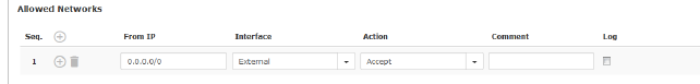
From IP
|
Enter the address of the computer or network from which access is permitted or forbidden in this field.
The following options are available:
IP address: 0.0.0.0/0 means all addresses. To specify an address area, use CIDR format, see "CIDR (Classless Inter-Domain Routing)" on page 34.
|
|
|
Interface
|
Internal / External / DMZ / VPN
Specifies to which interface the rule should apply.
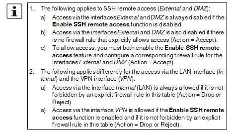
If no rules are set or if no rule applies, the following default settings apply:
–SSH access via Internal and VPN is permitted.
–SSH access via External and DMZ is denied.
Specify the access options according to your requirements.
|
|
|
Action
|
Options:
–Accept means that the data packets may pass through.
–Reject means that the data packets are sent back and the sender is informed of their rejection. (In Stealth mode, Reject has the same effect as Drop.)
–Drop means that the data packets are not permitted to pass through. They are discarded, which means that the sender is not informed of their whereabouts.
|
|
|
Comment
|
Freely selectable comment for this rule.
|
|
|
Log
|
For each individual firewall rule, you can specify whether the use of the rule:
–Should be logged – activate Log function
–Should not be logged – deactivate Log function (default)
|
|
RADIUS authentication
|
Users can be authenticated via a RADIUS server when they log in. This also applies for users who want to access the mGuard via shell access using SSH. The password is checked locally in the case of predefined users (root, admin, netadmin and audit).
|
|
|
|
|
Use RADIUS authentication for shell access
|
If set to No, the passwords of users who log in via shell access are checked via the local database on the mGuard.
Select Yes for users to be authenticated via a RADIUS server. This also applies for users who want to access the mGuard via shell access using SSH. The password is only checked locally in the case of predefined users (root, admin, netadmin, audit).
The netadmin and audit authorization levels relate to access rights with the mGuard device manager (FL MGUARD DM UNLIMITED).
Under X.509 Authentication, if you set Enable X.509 certificates for SSH access to Yes, the X.509 authentication method can be used as an alternative. Which method is actually used by the user depends on how the user uses the SSH client.
When setting up RADIUS authentication for the first time, select Yes.
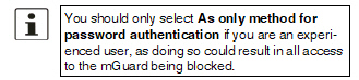
If you do intend to use the As only method for password authentication option when setting up RADIUS authentication, we recommend that you create a “Customized Default Profile” which resets the authentication method.
The predefined users (root, admin, netadmin, and audit) are then no longer able to log into the mGuard via SSH.
|
|
Management >> System Settings >> Shell Access
|
|
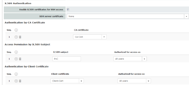
X.509 Authentication
|
X.509 certificates for SSH clients
The mGuard supports the authentication of SSH clients using X.509 certificates. It is sufficient to configure CA certificates that are required for the establishment and validity check of a certificate chain. This certificate chain must exist between the CA certificate on the mGuard and the X.509 certificate shown to the SSH client (see "Shell Access" on page 45).
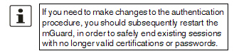
If the validity period of the client certificate is checked by the mGuard (see "Certificate Settings" on page 170), new CA certificates must be configured on the mGuard at some point. This must take place before the SSH clients use their new client certificates.
If CRL checking is activated (under Authentication >> Certificates >> Certificate Settings), one URL (where the corresponding CRL is available) must be maintained for each CA certificate. The URL and CRL must be published before the mGuard uses the CA certificates in order to confirm the validity of the certificates shown by the VPN partners.
|
|
|
|
|
Enable X.509 certificates for SSH access
|
If the function is deactivated, then only conventional authentication methods (user name and password or private and public keys) are permitted, not the X.509 authentication method.
If the function is activated, then the X.509 authentication method can be used in addition to conventional authentication methods (as also used when the function is deactivated).
If the function is activated, the following must be specified:
–How the mGuard authenticates itself to the SSH client according to X.509, see SSH server certificate (1)
–How the mGuard authenticates the remote SSH client according to X.509, see SSH server certificate (2)
|
|
|
SSH server certificate (1)
|
Specifies how the mGuard identifies itself to the SSH client.
Select one of the machine certificates from the selection list or the None entry.
None
When None is selected, the SSH server of the mGuard does not authenticate itself to the SSH client via the X.509 certificate. Instead, it uses a server key and thus behaves in the same way as older versions of the mGuard.
If one of the machine certificates is selected, this is also offered to the SSH client. The client can then decide whether to use the conventional authentication method or the method according to X.509.
The selection list contains the machine certificates that have been loaded on the mGuard under the Authentication >> Certificates menu item (see Page 165).
|
|
|
SSH server certificate (2)
|
Specifies how the mGuard authenticates the SSH client
The following definition relates to how the mGuard verifies the authenticity of the SSH client.
The table below shows which certificates must be provided for the mGuard to authenticate the SSH client if the SSH client shows one of the following certificate types when a connection is established:
–A certificate signed by a CA
–A self-signed certificate
For additional information about the table, see Section "Authentication >> Certificates" .
|
Authentication for SSH
|
The peer shows the following:
|
Certificate (specific to individual), signed by CA
|
Certificate (specific to individual), self-signed
|
|
The mGuard authenticates the peer using:
|

|

|
|
|
All CA certificates that form the chain to the root CA certificate together with the certificate shown by the peer
PLUS (if required)
Client certificates (remote certificates), if used as a filter
|
Client certificate (remote certificate)
|
According to this table, the certificates that must be provided are the ones the mGuard uses to authenticate the relevant SSH client.
The following instructions assume that the certificates have already been correctly installed on the mGuard (see "Authentication >> Certificates" ).
|

If the use of revocation lists (CRL checking) is activated under the "Authentication >> Certificates" , Certificate Settings menu item, each certificate signed by a CA that is “shown” by SSH clients is checked for revocations.
|
|
Management >> System Settings >> Shell Access
|
|
|
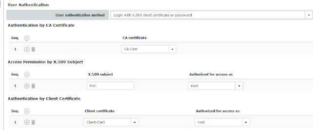
Authentication by CA Certificate
|
This configuration is only necessary if the SSH client shows a certificate signed by a CA.
All CA certificates required by the mGuard to form the chain to the relevant root CA certificate with the certificates shown by the SSH client must be configured.
The selection list contains the CA certificates that have been loaded on the mGuard under the "Authentication >> Certificates" menu item.
|
|
|
Access Permission by X.509 Subject
|
Enables a filter to be set in relation to the contents of the Subject field in the certificate shown by the SSH client. It is then possible to restrict or enable access for SSH clients, which the mGuard would accept in principle based on certificate checks:
–Restricted access to certain subjects (i.e., individuals) and/or to subjects that have certain attributes or
–Access enabled for all subjects (see glossary under "Subject, certificate" on page 321)
|
|
|
Access enabled for all subjects (i.e., individuals):
An * (asterisk) in the X.509 subject field can be used to specify that all subject entries in the certificate shown by the SSH client are permitted. It is then no longer necessary to identify or define the subject in the certificate.
Restricted access to certain subjects (i.e., individuals) or to subjects that have certain attributes:
In the certificate, the certificate owner is specified in the Subject field. The entry is comprised of several attributes. These attributes are either expressed as an object identifier (e.g., 132.3.7.32.1) or, more commonly, as an abbreviation with a corresponding value.
Example: CN=John Smith, O=Smith and Co., C=US
If certain subject attributes have very specific values for the acceptance of the SSH client by the mGuard, then these must be specified accordingly. The values of the other freely selectable attributes are entered using the * (asterisk) wildcard.
Example: CN=*, O=*, C=US (with or without spaces between attributes)
In this example, the attribute “C=US” must be entered in the certificate under “Subject”. It is only then that the mGuard would accept the certificate owner (subject) as a communication partner. The other attributes in the certificates to be filtered can have any value.
|
|
|
Authorized for access as
|
All users / root / admin / netadmin / audit
Additional filter which specifies that the SSH client has to be authorized for a specific administration level in order to gain access.
When establishing a connection, the SSH client shows its certificate and also specifies the system user for which the SSH session is to be opened (root, admin, netadmin, audit). Access is only granted if the entries match those defined here.
Access for all listed system users is possible when All users is set.
|
|
|
Authentication by Client Certificate
|
Configuration is required in the following cases:
–SSH clients each show a self-signed certificate.
–SSH clients each show a certificate signed by a CA. Filtering should take place: access is only granted to a user whose certificate copy is installed on the mGuard as the remote certificate and is provided to the mGuard in this table as the Client certificate.
This filter is not subordinate to the Subject filter. It resides on the same level and is allocated a logical OR function with the Subject filter.
The entry in this field defines which client certificate (remote certificate) the mGuard should adopt in order to authenticate the peer (SSH client).
The client certificate can be selected from the selection list. The selection list contains the client certificates that have been loaded on the mGuard under the "Authentication >> Certificates" menu item.
|
|
|
Authorized for access as
|
All users / root / admin / netadmin / audit
Filter which specifies that the SSH client has to be authorized for a specific administration level in order to gain access.
When establishing a connection, the SSH client shows its certificate and also specifies the system user for which the SSH session is to be opened (root, admin, netadmin, audit). Access is only granted if the entries match those defined here.
Access for all listed system users is possible when All users is set.
|
4.1.4E-Mail
|
Management >> System Settings >> E-Mail
|
|
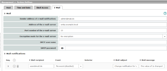
E-mail
(Make sure that the e-mail settings for the mGuard are correctly configured)
|
You can configure the mGuard to send e-mails via an e-mail server. Should certain events occur, notifications in plain text or machine-readable format can be sent to recipients that can be freely selected.
|
|
|
Sender address of e-mail notifications
|
E-mail address which is displayed as the sender from mGuard.
|
|
Address of the e-mail server
|
Address of the e-mail server
|
|
|
Port number of the e-mail server
|
Port number of the e-mail server
|
|
|
Encryption mode for the e-mail server
|
No encryption / TLS encryption / TLS encryption with StartTLS
Encryption mode for the e-mail server
|
|
|
SMTP user name
|
User identifier (login)
|
|
|
SMTP password
|
Password for the e-mail server
|
|
E-Mail notifications
|
Any e-mail recipients can be linked to predefined events and a freely definable message. The list is processed from top to bottom.
|
|
|
E-Mail recipient
|
Specifies the e-mail address.
|
|
|
Event
|
When the selected event occurs or the event is configured for the first time, the linked recipient address is selected and the event is sent to them as an e-mail.
An e-mail message can also be stored and sent. Some of the events listed depend on the hardware used.
A complete list of all events can be found under "Event table" on page 58.
|
|
|
Selector
|
A configured VPN connection can be selected here, which is monitored via e-mail.
|
|
|
E-Mail subject
|
Text appears in the subject line of the e-mail
The text is freely definable. You can use blocks from the event table which can be inserted as placeholders in plain text (\A and \V) or in machine-readable format (\a and \v). Time stamps in the form of a placeholder (\T or \t (machine readable)) can also be inserted.
|
|
|
E-Mail message
|
Here you can enter the text that is sent as an e-mail.
The text is freely definable. You can use blocks from the event table which can be inserted as placeholders in plain text (\A and \V) or in machine-readable format (\a and \v). Time stamps in the form of a placeholder can also be inserted in plain text (\T) or machine-readable format (\t).
|
Time stamp
Table 4-1Time stamp examples
|
Plain text \T
|
Machine readable \t (according to RFC-3339)
|
|
Monday, April 22, 2016 13:22:36
|
2016-04-22T11:22:36+0200
|
Event table
Table 4-2Event table
|
Plain text
|
Machine readable
|
|
\A = event
|
\V = value
|
\a = event
|
\v = value
|
|
State of the ECS
|
Not present
|
/ecs/status
|
1
|
|
Removed
|
2
|
|
Present and in sync
|
3
|
|
Not in sync
|
4
|
|
Generic error
|
8
|
|
Connectivity check result of the external interface
|
Connectivity check succeeded
|
/redundancy/cc/int/ok
|
yes
|
|
Connectivity check failed
|
no
|
|
Connectivity check result of the external interface
|
Connectivity check succeeded
|
/redundancy/cc/ext/ok
|
yes
|
|
Connectivity check failed
|
no
|
|
State of the alarm output
|
Alarm output closed / high [OK]
|
/ihal/contact
|
close
|
|
Alarm output is open / low [FAILURE]
|
open
|
|
Reason for activating the alarm output
|
No alarm
|
/ihal/contactreason
|
|
|
No network link on external interface
|
link_ext
|
|
No network link on internal interface
|
link_int
|
|
Power supply 1 out of order
|
psu1
|
|
Power supply 2 out of order
|
psu2
|
|
Board temperature exceeding configured bounds
|
temp
|
|
No network link on XF2
|
link_swp0
|
|
No network link on XF3
|
link_swp1
|
|
No network link on XF4
|
link_swp2
|
|
No network link on XF5
|
link_swp3
|
|
No network link on DMZ
|
link_dmz
|
|
Passwords not configured
|
password
|
|
State of the power supply 1
|
Power supply 1 working
|
/ihal/power/psu1
|
ok
|
|
Power supply 1 out of order
|
fail
|
|
State of the power supply 2
|
Power supply 2 working
|
/ihal/power/psu2
|
ok
|
|
Power supply 2 out of order
|
fail
|
|
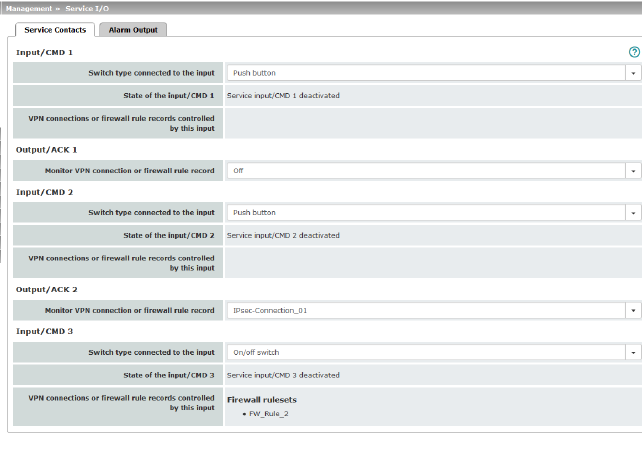
State of the input/CMD 1 (I1)
|
Service input/CMD1 (I1) activated
|
/ihal/service/cmd1
|
on
|
|
Service input/CMD1 (I1) deactivated
|
off
|
|
State of the input/CMD 2 (I2)
|
Service input/CMD2 (I2) activated
|
/ihal/service/cmd2
|
on
|
|
Service input/CMD2 (I2) deactivated
|
off
|
|
State of the input/CMD 3 (I3)
|
Service input/CMD3 (I3) activated
|
/ihal/service/cmd3
|
on
|
|
Service input/CMD3 (I3) deactivated
|
off
|
|
Board temperature
|
Temperature OK
|
/ihal/temperature/board_alarm
|
ok
|
|
Temperature too hot
|
hot
|
|
Temperature too cold
|
cold
|
|
Status of redundancy
|
The redundancy controller starts up
|
/redundancy/status
|
booting
|
|
No sufficient connectivity
|
faulty
|
|
No sufficient connectivity and waiting for a component
|
faulty_waiting
|
|
Synchronizing with active device
|
outdated
|
|
Synchronizing with active device and waiting for a component
|
outdated_waiting
|
|
On standby
|
on_standby
|
|
On standby and waiting for a component
|
on_standby_waiting
|
|
Becoming active
|
becomes_active
|
|
Actively forwarding network traffic
|
active
|
|
Actively forwarding network traffic and waiting for a component
|
active_waiting
|
|
IPsec VPN connection preparation state
|
Stopped
|
/vpn/con/*/armed
|
no
|
|
Started
|
yes
|
|
IPsec SA state of the VPN connection
|
No IPsec SAs established
|
/vpn/con/*/ipsec
|
down
|
|
Not all IPsec SAs established
|
some
|
|
All IPsec SAs established
|
up
|
|
Activation state of a firewall rule record
|
The state of the firewall rule sets has changed
|
/fwrules/*/state
|
inactive
|
|
active
|
|
OpenVPN connection activation state
|
Stopped
|
/openvpn/con/*/armed
|
no
|
|
Started
|
yes
|
|
OpenVPN connection state
|
Down
|
/openvpn/con/*/state
|
down
|
|
Established
|
up
|
4.2Management >> Web Settings
4.2.1General
|
Management >> Web Settings >> General
|
|
General
|
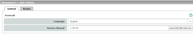
Language
|
If Automatic is selected in the list of languages, the device uses the language setting of the computer's web browser.
|
|
|
Session timeout
|
Specifies the period of inactivity after which the user will be automatically logged out of the mGuard web interface. Possible values: 15 to 86400 seconds (= 24 hours)
The entry can be in seconds [ss], minutes and seconds [mm:ss] or hours, minutes, and seconds [hh:mm:ss].
|
4.2.2Access
|

The mGuard must not be simultaneously configured via web access, shell access or SNMP. Simultaneous configuration via the different access methods might lead to unexpected results.
|
|
Management >> Web Settings >> Access
|
|
HTTPS Web Access
|
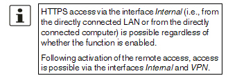
When HTTPS remote access is activated, the mGuard can be configured from remote computers via its web interface. Access is via a web browser (e.g., Mozilla Firefox, Google Chrome, Microsoft Edge).
HTTPS remote access is deactivated by default. Once activated it can be restricted to selected interfaces and networks.
|
|
|
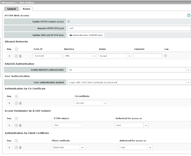
Enable HTTPS remote access
|
Activate the function to enable HTTPS remote access.
The firewall rules for the available interfaces must be defined accordingly in order to specify differentiated access options on the mGuard (see "Allowed Networks" on page 65).
In addition, the authentication rules under User authentication must be set, if necessary.
|
|
|
Remote HTTPS TCP port
|
Default: 443
If this port number is changed, the new port number only applies for access via the External, DMZ, and VPN interface. Port number 443 still applies for internal access.
The remote peer that implements remote access may have to specify the port number defined here after the IP address when entering the address.
Example: if this mGuard can be accessed over the Internet via address 123.124.125.21 and port number 443 has been specified for remote access, you do not need to enter this port number after the address in the web browser of the remote peer.
If a different port number is used, it should be entered after the IP address, e.g.: https://123.124.125.21:442/
|
|
|
Update SSH and HTTPS keys
|
Generate new 2048 bit keys
Keys that have been generated using an older firmware version might be weak and should be renewed.
•Click on this button to generate a new key.
•Note the fingerprints of the new keys generated.
•Log in via HTTPS and compare the certificate information provided by the web browser.
|
|
Allowed Networks
|
HTTPS access to the mGuard can be restricted to selected interfaces and networks by means of firewall rules.
If multiple firewall rules are defined, these are queried starting from the top of the list of entries until an appropriate rule is found. This rule is then applied. If the list of rules contains further subsequent rules that could also apply, these rules are ignored.
The following options are available:
|
|
|
|
|
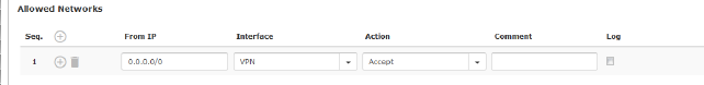
From IP
|
Enter the address of the computer or network from which access is permitted or forbidden in this field.
IP address: 0.0.0.0/0 means all addresses. To specify an address area, use CIDR format – see "CIDR (Classless Inter-Domain Routing)" on page 34.
|
|
|
Interface
(This option varies depending on the device and licenses installed.)
|
Internal / External / DMZ / VPN
Specifies to which interface the rule should apply.
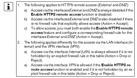
If no rules are set or if no rule applies, the following default settings apply:
–HTTPS access via Internal and VPN is permitted.
–HTTPS access via External and DMZ is denied.
Specify the access options according to your requirements.
|
|
|
Action
|
–Accept means that the data packets may pass through.
–Reject means that the data packets are sent back and the sender is informed of their rejection. (In Stealth mode, Reject has the same effect as Drop.)
–Drop means that the data packets are not permitted to pass through. They are discarded, which means that the sender is not informed of their whereabouts.
|
|
|
Comment
|
Freely selectable comment for this rule.
|
|
|
Log
|
For each individual firewall rule, you can specify whether the use of the rule:
–Should be logged – activate Log function
–Should not be logged – deactivate Log function (default)
|
|
RADIUS authentication
|
Users can be authenticated via a RADIUS server when they log in. The password is only checked locally in the case of predefined users (root, admin, netadmin, audit, and user).
|
|
|
|
|
Enable RADIUS authentication
|
If the function is activated, the passwords of users who log in via HTTPS are checked via the local database.
The User authentication method can only be set to Login restricted to X.509 client certificate if No is selected.
Select Yes for users to be authenticated via the RADIUS server. The password is only checked locally in the case of predefined users (root, admin, netadmin, audit, and user).
The netadmin and audit authorization levels relate to access rights with the mGuard device manager (FL MGUARD DM UNLIMITED).
When setting up RADIUS authentication for the first time, select Yes.
If you do intend to use the As only method for password authentication option when setting up RADIUS authentication, we recommend that you create a “Customized Default Profile” which resets the authentication method.
If you have selected RADIUS authentication as the only method for checking the password, it may no longer be possible to access the mGuard. For example, this may be the case if you set up the wrong RADIUS server or convert the mGuard. The predefined users (root, admin, netadmin, audit, and user) are then no longer accepted.
|
|
Management >> Web Settings >> Access
|
|
User Authentication
(This menu item is not part of the FL MGUARD 2000 functionality.)
|
You can specify whether the mGuard user authenticates their login with a password, an X.509 user certificate or a combination of the two.
|
|
|
|
Specifies how the local mGuard authenticates the remote peer
|
User authentication method
|
Login with password
Specifies that the remote mGuard user must use a password to log into the mGuard. The password is specified under the Authentication >> Administrative Users menu (see Page 155). The option of RADIUS authentication is also available (see Page 162).
Depending on which user identifier is used to log in (user or administrator password), the user has the appropriate rights to operate and/or configure the mGuard accordingly.
Login with X.509 client certificate or password
User authentication is by means of login with a password (see above) or
The user’s web browser authenticates itself using an X.509 certificate and a corresponding private key. Additional details must be specified below.
The use of either method depends on the web browser of the remote user. The second option is used when the web browser provides the mGuard with a certificate.
|
|
|
|
Login restricted to X.509 client certificate
The user's web browser must use an X.509 certificate and the corresponding private key to authenticate itself. Additional details must be specified here.
|
If the following User authentication methods are defined:
–Login restricted to X.509 client certificate
–Login with X.509 client certificate or password
You must then specify how the mGuard authenticates the remote user according to X.509.
The table below shows which certificates must be provided for the mGuard to authenticate the user (access via HTTPS) if the user or their web browser shows one of the following certificate types when a connection is established:
–A certificate signed by a CA
–A self-signed certificate
For additional information about the table, see "Authentication >> Certificates" on page 165.
X.509 authentication for HTTPS
|
The peer shows the following:
|
Certificate (specific to individual), signed by CA1
|
Certificate (specific to individual), self-signed
|
|
The mGuard authenticates the peer using:
|

|

|
|
|
All CA certificates that form the chain to the root CA certificate together with the certificate shown by the peer
PLUS (if required)
Client certificates (remote certificates), if used as a filter
|
Client certificate (remote certificate)
|
According to this table, the certificates that must be provided are the ones the mGuard uses to authenticate a remote user (access via HTTPS) or their web browser.
The following instructions assume that the certificates have already been correctly installed on the mGuard (see "Authentication >> Certificates" on page 165).
|

If the use of revocation lists (CRL checking) is activated under the Authentication >> Certificates, Certificate Settings menu item, each certificate signed by a CA that is “shown” by the HTTPS clients must be checked for revocations.
|
|
Management >> Web Settings >> Access
|
|
|
Authentication by CA Certificate
|
This configuration is only necessary if the user (access via HTTPS) shows a certificate signed by a CA.
All CA certificates required by the mGuard to form the chain to the relevant root CA certificate with the certificates shown by the user must be configured.
If the web browser of the remote user also provides CA certificates that contribute to forming the chain, then it is not necessary for these CA certificates to be installed on the mGuard and referenced at this point.
However, the corresponding root CA certificate must be installed on the mGuard and made available (referenced) at all times.
|
|
|
Access Permission by X.509 Subject
|
Enables a filter to be set in relation to the contents of the Subject field in the certificate shown by the web browser/HTTPS client.
It is then possible to restrict or enable access for the web browser/HTTPS client, which the mGuard would accept in principle based on certificate checks:
–Restricted access to certain subjects (i.e., individuals) and/or to subjects that have certain attributes or
–Access enabled for all subjects (see glossary under "Subject, certificate" on page 321)
|
|
|
|
Access enabled for all subjects (i.e., individuals):
An * (asterisk) in the X.509 subject field can be used to specify that all subject entries in the certificate shown by the web browser/HTTPS client are permitted. It is then no longer necessary to identify or define the subject in the certificate.
|
|
|
|
Restricted access to certain subjects (i.e., individuals) and/or to subjects that have certain attributes:
In the certificate, the certificate owner is specified in the Subject field. The entry is comprised of several attributes. These attributes are either expressed as an object identifier (e.g., 132.3.7.32.1) or, more commonly, as an abbreviation with a corresponding value.
Example: CN=John Smith, O=Smith and Co., C=US
If certain subject attributes have very specific values for the acceptance of the web browser by the mGuard, then these must be specified accordingly. The values of the other freely selectable attributes are entered using the * (asterisk) wildcard.
Example: CN=*, O=*, C=US (with or without spaces between attributes)
In this example, the attribute “C=US” must be entered in the certificate under “Subject”. It is only then that the mGuard would accept the certificate owner (subject) as a communication partner. The other attributes in the certificates to be filtered can have any value.
With HTTPS, the web browser of the accessing user does not specify which user or administrator rights it is using to log in. These access rights are assigned by setting filters here (under “Authorized for access as”).
This has the following result: if there are several filters that “let through” a certain user, then the first filter applies.
|
|
|
|
The user is assigned the access rights as defined by this filter. This could differ from the access rights assigned to the user in the subsequent filters.
|
|
|
Authorized for access as
|
root / admin / netadmin / audit / user
Specifies which user or administrator rights are granted to the remote user.
For a description of the root, admin, and user authorization levels, see "Authentication >> Administrative Users" on page 155.
The netadmin and audit authorization levels relate to access rights with the mGuard device manager (FL MGUARD DM UNLIMITED).
|
|
|
Authentication by Client Certificate
|
Configuration is required in the following cases:
–Remote users each show a self-signed certificate.
–Remote users each show a certificate signed by a CA. Filtering should take place: access is only granted to a user whose certificate copy is installed on the mGuard as the remote certificate and is provided to the mGuard in this table as the Client certificate.
If used, this filter has priority over the Subject filter in the table above.
The entry in this field defines which remote certificate the mGuard should adopt in order to authenticate the peer (web browser of the remote user).
The client certificate can be selected from the selection list.
The selection list contains the client certificates that have been loaded on the mGuard under the "Authentication >> Certificates" menu item.
|
|
|
Authorized for access as
|
root / admin / netadmin / audit / user
Specifies which user or administrator rights are granted to the remote user.
For a description of the root, admin, and user authorization levels, see "Authentication >> Administrative Users" on page 155.
The netadmin and audit authorization levels relate to access rights with the mGuard device manager (FL MGUARD DM UNLIMITED).
|
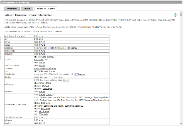
4.3Management >> Terms of License
Lists the licenses of the external software used on the mGuard. The software is usually open-source software (for the current list see also application note AH EN MGUARD3 MG10 LICENSES "License Information - Free and Open Source Software" (available in the PHOENIX CONTACT Web Shop e.g. at phoenixcontact.net/product/1357828).
4.4Management >> Update
|

Use the respective latest firmware version
Because security-relevant improvements are added to the product with each new firmware version, the latest firmware version should always be used.
Phoenix Contact regularly provides firmware updates. You will find these on the product page of the respective device (e.g., phoenixcontact.net/product/1357840).
•Ensure that the firmware of all devices used is always up to date.
•Observe the Change Notes/Release Notes for the respective firmware version.
•Observe the safety notes published on the Phoenix Contact Product Security Incident Response Team (PSIRT) website regarding any published vulnerabilities.
|
|

To ensure that the downloaded firmware or update file has not been modified by third parties during the download, you can compare the SHA256 checksum of the file with the checksum specified on the corresponding product page (phoenixcontact.com/product/<item number>).
|
|

An update to the current firmware version is possible from all firmware versions starting from mGuard 10.0.0. Downgrading to a lower firmware version is generally not possible.
|
|

NOTE: The device may be damaged if the update process is interrupted.
Do not switch the device off or interrupt the power supply to the device during the update process.
|
4.4.1Overview
|
Management >> Update >> Overview
|
|
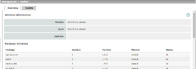
Version information
|
Lists information about the firmware version of the mGuard.
|
|
|
Version
|
The current software version of the mGuard device.
|
|
|
Base
|
The software version that was originally used to flash this device.
|
|
|
Updates
|
List of updates that have been installed on the base.
|
|
Package Versions
|
Lists the individual software modules of the mGuard. This information may be needed if support is required.
|
4.4.2Update
Firmware updates with firewall redundancy enabled
|

NOTE: Only the inactive device of a redundancy pair can be updated.
|
Procedure
•Always update the inactive device of the redundancy pair first.
This device will automatically become the active device after a successful update.
•Now, start the update for the other, now inactive, device.
•Check whether both devices have been successfully updated.
Updating the firmware
There are two options for performing a firmware update:
1.You have the current package set file on your computer (the file name ends with “.tar.gz”) and you perform a local update.
2.The mGuard downloads a firmware update of your choice from the update server via the Internet and installs it
|

NOTE: Do not interrupt the power supply to the mGuard during the update process. Otherwise, the device could be damaged and may have to be reactivated by the manufacturer.
|
|

Depending on the size of the update, the process may take several minutes.
|
|

A message is displayed if a restart is required after completion of the update.
|
.
|
Management >> Update
|
|
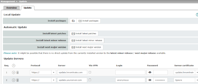
Local Update
|
Install packages
|
To install the packages, proceed as follows:
•Click on the  No file selected icon, select the file and open it. No file selected icon, select the file and open it.
The file name of the update file depends on the device platform and the currently installed firmware version (see also Application Note Update FL_TC MGUARD devices – AH EN MGUARD UPDATE).
Example: update-10.0-10.1.0.default.aarch64.tar.gz
•Then click on the Install packages button.
|
|
Automatic Update
|
Using the automatic update, the mGuard independently determines the required package set.
|
|
|
Install latest patches
|
Patch releases resolve errors in previous versions and have a version number which only changes in the third digit position. Example: Version 10.0.1 is a patch release for Version 10.0.0.
|
|
|
Install latest minor release
|
Minor and major releases supplement the mGuard with new properties or contain changes that affect the behavior of the mGuard.
Their version number changes in the first or second digit position. Example: Version 10.1.0 is a minor release for Version 10.0.1.
|
|
|
Install next major version
|
Example: Version 11.6.0 is a major release for Version 10.1.0.
|
|
Update Servers
|
Specify from which servers an update may be performed.
The following options are available:
|
|
|
Protocol
|
The update can be performed via HTTPS, HTTP, FTP or TFTP.
|
|
|
Server
|
Host name or IP address of the server that provides the update files.
|
|
|
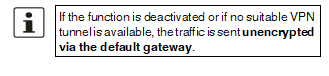
Via VPN
|
The update server's request is, where possible, carried out via a VPN tunnel.
When the function is activated, communication with the server is always via an encrypted VPN tunnel if a suitable one is available.
|
|
|
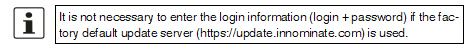
Login
|
Login for the server.
|
|
|
Password
|
Password for login.
|
|
|
Server certificate
|
To ensure that a secure HTTPS connection is established to the configured update server, the corresponding server certificate of the update server must be checked by the mGuard device.
The update server is authenticated either via a corresponding remote certificate or via a CA certificate. The certificate must be uploaded to the mGuard device so that it can be selected for verification of the server certificate in the drop-down list (see Section 6.4.4, "Remote Certificates"und Section 6.4.3, "CA Certificates").
If the "Ignore" option is selected, no check takes place.
|
4.5Management >> Configuration Profiles
4.5.1Configuration Profiles
You can save the settings of the mGuard as a configuration profile under any name on the mGuard. It is possible to create multiple configuration profiles. You can then switch between different profiles as required, for example, if the mGuard is used in different environments.
Furthermore, you can also save the configuration profiles as files on your configuration computer. Alternatively, these configuration files can be loaded onto the mGuard and activated.
In addition, you can restore the Factory Default settings at any time.
The devices also allow the configuration profiles to be stored on external configuration storage (ECS).
|

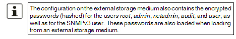
When a configuration profile is saved, the passwords used for authenticating administrative access to the mGuard (Root password, Admin password, SNMPv3 password) are not saved.
|
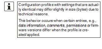
|

It is possible to load and activate a configuration profile that was created under an older firmware version. However, the reverse is not true – a configuration profile created under a newer firmware version should not be loaded and will be rejected.
|
Encrypted configuration memory
Configuration profiles can be encrypted and thus made associable for each device individually. This makes rollout easier.
You can save several mGuard configurations on an SD card and then use it to start up all mGuards. During the startup process, the mGuard finds the relevant valid configuration on the SD card. This is loaded, decrypted, and used as the valid configuration (see "Encrypt the data on the ECS" on page 83.)
Recovery procedure
Before performing the recovery procedure, the current device configuration is stored in a new configuration profile (“Recovery DATE”). Following the recovery procedure, the device starts with the default settings.
Following the recovery procedure, the configuration profile with the designation “Recovery DATE” appears in the list of configuration profiles and can be restored with or without changes.
|
Management >> Configuration Profiles
|
|
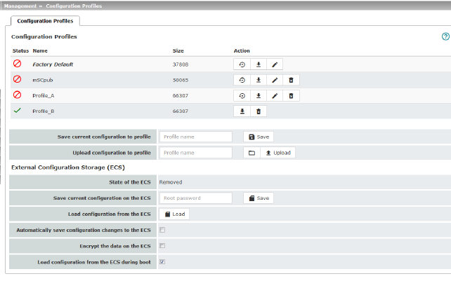
Configuration Profiles
|
At the top of the page there is a list of the configuration profiles that are stored on the mGuard, e.g., the Factory Default configuration profile. If any configuration profiles have been saved by the user (see below), they will be listed here.
Active configuration profile: the configuration profile that is currently enabled has an Active symbol at the start of the entry. If a configuration is modified in such a way that it corresponds to a stored configuration profile, the Active symbol appears next to it after the changes have been applied . .
Configuration profiles that are stored on the mGuard can be:
–Enabled (Restore profile) 
–Downloaded as an atv file on the connected configuration computer 
–Viewed and edited (Edit profile) 
–Deleted 
|
|
|
Download configuration profile as an atv file
•Click on the name of the configuration profile in the list.
The configuration profile is downloaded as an atv file and can be analyzed with a text editor.
|
|
|
View and edit configuration profile before restoring it (Edit profile )
•Click on the  Edit profile icon to the right of the configuration profile name. Edit profile icon to the right of the configuration profile name.
The configuration profile is loaded, but not activated yet. All entries that contain changes to the configuration currently used are highlighted in green on the relevant page and in the associated menu path. The changes displayed can be applied as they are or with further modifications, or they can be discarded:
–To apply the entries for the loaded profile (with further modifications, where applicable), click on the  Save icon. Save icon.
–To discard all changes, click on the  Reset icon. Reset icon.
|
|
|
Enable the factory default or a configuration profile saved on the mGuard by the user (Restore profile)
•Click on the  Restore profile icon to the right of the configuration profile name. Restore profile icon to the right of the configuration profile name.
The corresponding configuration profile is restored without a safety prompt being displayed and is activated immediately.
|
|
|
Save configuration profile as a file on the configuration computer
•Click on the  Download profile icon to the right of the configuration profile name. Download profile icon to the right of the configuration profile name.
•In the dialog box that is displayed, where appropriate specify the file name and storage location where the configuration profile is to be saved as a file. (The file name can be freely selected.)
|
|
|
Delete configuration profile
•Click on the  Delete profile icon to the right of the configuration profile name. Delete profile icon to the right of the configuration profile name.
|
|
|
Save current configuration to profile
|
Save current configuration as a profile on the mGuard
•Enter the desired profile name in the Profile name field next to “Save current configuration to profile”.
•Click on the  Save button. Save button.
The configuration profile is saved on the mGuard. The profile name appears in the list of configuration profiles stored on the mGuard.
|
|
|
Upload configuration to profile
|
Upload a configuration profile that has been saved to a file on the configuration computer
Requirement: a configuration profile has been saved on the configuration computer as a file according to the procedure described above.
•Enter the desired profile name that is to be displayed in the Profile name field next to “Upload configuration to profile”.
•Click on the  No file selected icon and select and open the relevant file in the dialog box that is displayed. No file selected icon and select and open the relevant file in the dialog box that is displayed.
•Click on the  Upload button. Upload button.
The configuration profile is loaded on the mGuard, and the name assigned in step 1 appears in the list of profiles that are stored.
|
|
External Configuration Storage (ECS)
|
Configuration profiles stored on the mGuard can be exported to an SD card serving as an external configuration storage (ECS) from where they can be imported onto mGuard devices again.
Name of the exported file: ECS.tgz
Technical requirements of SD cards:
–FAT file system on the first partition
SD cards certified and approved by Phoenix Contact: see section „Accessories“ on the product pages at phoenixcontact.net/products
To import the file onto an mGuard device, the SD card must be inserted into the mGuard.
The configuration can be:
–Automatically loaded, decrypted, and used as the active configuration when the device is started
–Loaded and activated via the web interface
|
|
|
State of the ECS
|
The current state is updated dynamically. (See "State of the ECS" in "Event table" on page 58).
|
|
|
Save current configuration on the ECS
|
When replacing the original device with a replacement device, the configuration profile of the original device can be applied using the ECS. To do so, the replacement device must still use “root” as the password for the “root” user.
If the root password on the replacement device is not “root”, this password must be entered in the “Root password” field. Click on the  Save button to apply the entry. Save button to apply the entry.
Complex configurations, e.g. with a huge number of configured firewall rules and/or VPN connections, can lead to large configuration profiles.
|
|
|
Load configuration from the ECS
|
If there is a configuration profile on an inserted or connected ECS storage medium, clicking on the  “Load” button imports it to the mGuard where it is enabled as the active profile. “Load” button imports it to the mGuard where it is enabled as the active profile.
The loaded configuration profile does not appear in the list of configuration profiles stored on the mGuard.
|
|
|
Automatically save configuration changes to the ECS
|
When the function is activated, the configuration changes are automatically saved to the ECS, i.e., the ECS always stores the profile currently used.
The mGuard only uses the automatically stored configuration profiles on startup if the original password (“root”) is still set on the mGuard for the “root” user.
Configuration changes are made even if the ECS is disconnected, full or defective. The corresponding error messages are displayed in the Logging menu (see "Logging >> Browse Local Logs" on page 295).
Activation of the new setting extends the response time of the user interface when changing any settings.
|
|
|
Encrypt the data on the ECS
|
When the function is activated, the configuration changes are encrypted and stored on an ECS. This makes mGuard rollout easier.
You can save several mGuard configurations on an SD card and then use it to start up all mGuards. During the startup process, the mGuard finds the relevant valid configuration on the configuration storage. This is loaded, decrypted, and used as the valid configuration.
|
|
|
Load configuration from the ECS during boot
|
When the function is activated, the ECS is accessed when booting the mGuard. The configuration profile is loaded from the ECS onto the mGuard, decrypted if necessary, and used as the valid configuration.
|
4.6Management >> SNMP
|

The mGuard must not be simultaneously configured via web access, shell access or SNMP. Simultaneous configuration via the different access methods might lead to unexpected results.
|
|

Unlike the SNMPv3 protocol, the older versions SNMPv1/SNMPv2 do not use authentication or encryption, and are therefore not considered to be secure.
The SNMPv1/2 protocol should only be used in a secure network environment that is entirely under the control of the operator.
SNMPv3 is not supported by all management consoles, however.
|
The Simple Network Management Protocol (SNMP) is primarily used in more complex networks to monitor or configure the state and operation of devices.
It is also possible to execute Actions on the mGuard using the SNMP protocol. Documentation of the actions that can be executed is available via the corresponding MIB file.
MIB file
To configure, monitor or control the mGuard via an SNMP client using the SNMP protocol, the corresponding MIB file must be imported into the SNMP client. MIB files are provided in a ZIP file together with the firmware or firmware updates. They can be downloaded from the manufacturer's website via the corresponding product pages:
phoenixcontact.net/products.
4.6.1Query
|

Processing an SNMP request may take more than one second. However, this value corresponds to the default timeout value of some SNMP management applications.
•If you experience timeout problems, set the timeout value of your management application to values between 3 and 5 seconds.
|
|
Management >> SNMP >> Query
|
|
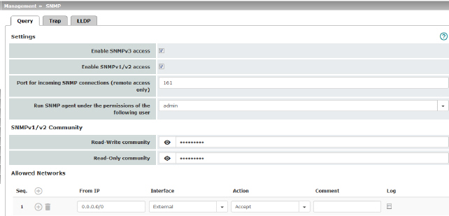
Settings
|
Enable SNMPv3 access
|
Activate the function if you wish to allow monitoring of the mGuard via SNMPv3.
Access via SNMPv3 requires authentication with a user name and password. The default setting for the access data is as follows:
User name: admin
Password: SnmpAdmin
(It is case-sensitive.)
The SNMPv3 access data user name and password can be changed via the web interface, an ECS configuration, or a rollout script.
Administration of SNMPv3 users via SNMPv3 USM is not possible.
The addition of further SNMPv3 users is not currently supported.
MD5 is used for the authentication process; DES is supported for encryption.
|
|
|
Enable SNMPv1/v2 access
|
Activate the function if you wish to allow monitoring of the mGuard via SNMPv1/v2.
You must also enter the login data under SNMPv1/v2 Community.
|
|
|
Port for incoming SNMP connections
|
Default: 161
If this port number is changed, the new port number only applies for access via the External, DMZ, and VPN interface. Port number 161 still applies for internal access.
The remote peer that implements remote access may have to specify the port number defined here when entering the address.
|
|
|
Run SNMP agent under the permissions of the following user
|
admin / netadmin
Specifies which permissions are used to run the SNMP agent.
|
|
SNMPv3 access data
|
User name
|
Changes the currently assigned SNMPv3 user name.
|
|
|
Password
|
Changes the currently assigned SNMPv3 password.
The password can only be written but not read out (write only).
|
|
SNMPv1/v2 Community
|
Read-Write community
|
Enter the required login data in this field.
|
|
|
Read-Only community
|
Enter the required login data in this field.
|
|
Allowed Networks
|
Lists the firewall rules that have been set up. These apply for incoming data packets of an SNMP access attempt.
If no rules are set or if no rule applies, the following default settings apply:
–SNMP access via Internal and VPN is permitted.
–SNMP access via External and DMZ is denied.
Specify the monitoring options according to your requirements.
The rules specified here only take effect if the Enable SNMPv3 access or Enable SNMPv1/v2 access function is activated.
If multiple firewall rules are defined, these are queried starting from the top of the list of entries until an appropriate rule is found. This rule is then applied. If the list of rules contains further subsequent rules that could also apply, these rules are ignored.
|
|
|
From IP
|
Enter the address of the computer or network from which access is permitted or forbidden in this field.
The following options are available:
–An IP address.
–To specify an address area, use CIDR format (see "CIDR (Classless Inter-Domain Routing)" on page 34).
–0.0.0.0/0 means all addresses.
|
|
|
Interface
|
Internal / External / DMZ / VPN
Specifies to which interface the rule should apply.
If no rules are set or if no rule applies, the following default settings apply:
–SNMP access via Internal and VPN is permitted.
–SNMP access via External and DMZ is denied.
Specify the monitoring options according to your requirements.
|
|
|
Action
|
Accept means that the data packets may pass through.
Reject means that the data packets are sent back and the sender is informed of their rejection. (In Stealth mode, Reject has the same effect as Drop.)
Drop means that the data packets are not permitted to pass through. They are discarded, which means that the sender is not informed of their whereabouts.
|
|
|
Comment
|
Freely selectable comment for this rule.
|
|
|
Log
|
For each individual firewall rule, you can specify whether the use of the rule:
–Should be logged – activate Log function
–Should not be logged – deactivate Log function (default)
|
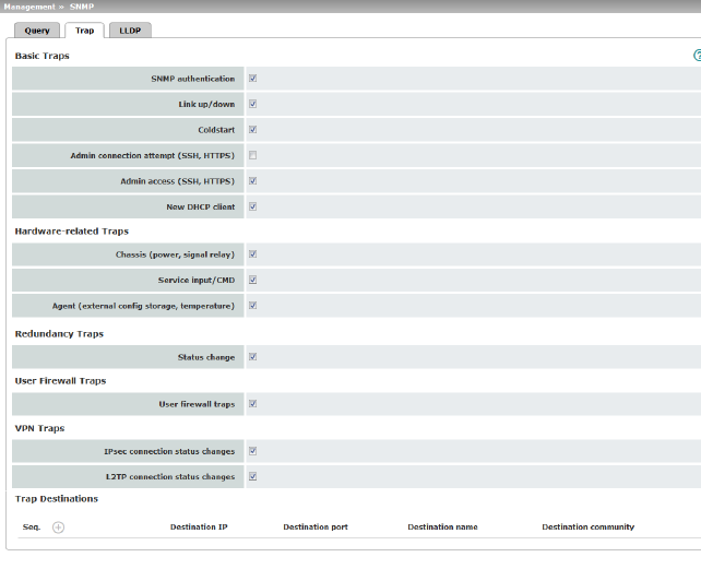
4.6.2Trap
In certain cases, the mGuard can send SNMP traps. SNMP traps are only sent if the SNMP request is activated.
The traps correspond to SNMPv1. The trap information for each setting is listed below. A more detailed description can be found in the MIB that belongs to the mGuard.
|

If SNMP traps are sent to the peer via a VPN tunnel, the IP address of the peer must be located in the network that is specified as the Remote network in the definition of the VPN connection.
The internal IP address must be located in the network that is specified as Local in the definition of the VPN connection (see IPsec VPN >> Connections >> Edit >> General).
|
–If the IPsec VPN >> Connections >> Edit >> General, Local option is set to 1:1 NAT (see Page 238), the following applies:
The internal IP address must be located in the specified local network.
–If the IPsec VPN >> Connections >> Edit >> General, Remote option is set to 1:1 NAT (see Page 240), the following applies:
The IP address of the remote log server must be located in the network that is specified as Remote in the definition of the VPN connection.
|
Management >> SNMP >> Trap
|
|
Basic Traps
|
SNMP authentication
|
Trap description
–enterprise-oid : mGuardInfo
–generic-trap : authenticationFailure
–specific-trap : 0
Sent if an unauthorized station attempts to access the mGuard SNMP agent.
|
|
|
Link up/down
|
Trap description
–enterprise-oid : mGuardInfo
–generic-trap : linkUp, linkDown
–specific-trap : 0
Sent when the connection to a port is interrupted (linkDown) or restored (linkUp).
|
|
|
Cold restart
|
Trap description
–enterprise-oid : mGuardInfo
–generic-trap : coldStart
–specific-trap : 0
Is sent after a cold restart or warm start.
|
|
|
Admin connection attempt (SSH, HTTPS)
|
Trap description
–enterprise-oid : mGuard
–generic-trap : enterpriseSpecific
–specific-trap : mGuardHTTPSLoginTrap (1)
–additional : mGuardHTTPSLastAccessIP
Is sent if someone has tried successfully or unsuccessfully (e.g., using an incorrect password) to open an HTTPS session. The trap contains the IP address from which the attempt was issued.
|
|
|
|
–enterprise-oid : mGuard
–generic-trap : enterpriseSpecific
–specific-trap : mGuardShellLoginTrap (2)
–additional : mGuardShellLastAccessIP
Is sent when someone opens the shell via SSH interface. The trap contains the IP address of the login request.
|
|
|
Admin access (SSH, HTTPS)
|
Trap description
–enterprise-oid : mGuard
–generic-trap : enterpriseSpecific
–specific-trap : mGuardTrapSSHLogin
–additional : mGuardTResSSHUsername
mGuardTResSSHRemoteIP
Is sent when someone accesses the mGuard via SSH.
|
|
|
|
–enterprise-oid : mGuard
–generic-trap : enterpriseSpecific
–specific-trap : mGuardTrapSSHLogout
–additional : mGuardTResSSHUsername
mGuardTResSSHRemoteIP
Is sent when access to the mGuard via SSH is terminated.
|
|
|
New DHCP client
|
Trap description
–enterprise-oid : mGuard
–generic-trap : enterpriseSpecific
–specific-trap : 3
–additional : mGuardDHCPLastAccessMAC
Is sent when a DHCP request is received from an unknown client.
|
|
Hardware-related Traps
|
Chassis (power, signal relay)
|
Trap description
–enterprise-oid : mGuardTrapSenderIndustrial
–generic-trap : enterpriseSpecific
–specific-trap : mGuardTrapIndustrialPowerStatus (2)
–additional : mGuardTrapIndustrialPowerStatus
Sent when the system registers a power failure.
|
|
|
|
–enterprise-oid : mGuardTrapSenderIndustrial
–generic-trap : enterpriseSpecific
–specific-trap : mGuardTrapSignalRelais (3)
–additional : mGuardTResSignalRelaisState
(mGuardTEsSignlalRelaisReason, mGuardTResSignal RelaisReasonIdx)
Sent after the signal contact is changed and indicates the current status (0 = Off, 1 = On).
|
|
|
Service input/CMD
(Alternative designation for service input: „I“)
|
Trap description
–enterprise-oid : mGuardTrapCMD
–generic-trap : enterpriseSpecific
–specific-trap : mGuardTrapCMDStateChange (1)
–additional : mGuardCMDState
Is sent if a service input/CMD is switched by a switch or button. A trap is sent during every switching procedure.
|
|
|
Agent (external config storage, temperature)
|
Trap description
–enterprise-oid : mGuardTrapIndustrial
–generic-trap : enterpriseSpecific
–specific-trap : mGuardTrapIndustrialTemperature (1)
–additional : mGuardSystemTemperature,
mGuardTrapIndustrialTempHiLimit,
mGuardTrapIndustrialLowLimit
Indicates the temperature in the event of the temperature exceeding the specified limit values.
|
|
|
|
–enterprise-oid : mGuardTrapIndustrial
–genericTrap : enterpriseSpecific
–specific-trap : mGuardTrapAutoConfigAdapterState (4)
–additional : mGuardTrapAutoConfigAdapter Change
Is sent after access to the ECS.
|
|
Userfirewall traps
(Not part of the FL MGUARD 2000 series.)
|
Userfirewall traps
|
Trap description
–enterprise-oid : mGuardTrapUserFirewall
–generic-trap : enterpriseSpecific
–specific-trap : mGuardTrapUserFirewallLogin (1)
–additional : mGuardTResUserFirewallUsername,
mGuardTResUserFirewallSrcIP,
mGuardTResUserFirewallAuthenticationMethod
Is sent when a user logs into the user firewall.
|
|
|
|
–enterprise-oid : mGuardTrapUserFirewall
–generic-trap : enterpriseSpecific
–specific-trap : mGuardTrapUserFirewallLogout (2)
–additional : mGuardTResUserFirewallUsername,
mGuardTResUserFirewallSrcIP,
mGuardTResUserFirewallLogoutReason
Is sent when a user logs out of the user firewall.
|
|
|
|
–enterprise-oid : mGuardTrapUserFirewall
–generic-trap : enterpriseSpecific
–specific-trap : mGuardTrapUserFirewallAuthError TRAP-TYPE (3)
–additional : mGuardTResUserFirewallUsername,
mGuardTResUserFirewallSrcIP,
mGuardTResUserFirewallAuthenticationMethod
Is sent in the event of an authentication error.
|
|
Redundancy Traps
(Not for devices of the FL MGUARD 2000 series)
|
Status change
|
Trap description
–enterprise-oid : mGuardTrapRouterRedundancy
–generic-trap : enterpriseSpecific
–specific-trap : mGuardTrapRouterRedBackupDown
–additional : mGuardTResRedundacyBackupDown
This trap is sent when the backup device (secondary mGuard) cannot be reached by the master device (primary mGuard). (The trap will only be sent if ICMP checks are activated.)
–enterprise-oid : mGuardTrapRouterRedundancy
–generic-trap : enterpriseSpecific
–specific-trap : mGuardTrapRRedundancyStatusChange
–additional : mGuardRRedStateSSV,
mGuardRRedStateACSummary,
mGuardRRedStateCCSummary,
mGuardRRedStateStateRepSummary
Is sent when the status of the HA cluster has changed.
|
|
VPN Traps
|
IPsec connection status changes
|
Trap description
–enterprise-oid : mGuardTrapVPN
–genericTrap : enterpriseSpecific
–specific-trap : mGuardTrapVPNIKEServerStatus (1)
–additional : mGuardTResVPNStatus
Is sent when the IPsec IKE server is started or stopped.
|
|
|
|
–enterprise-oid : mGuardTrapVPN
–genericTrap : enterpriseSpecific
–specific-trap : mGuardTrapVPNIPsecConnStatus (2)
–additional : mGuardTResVPNName,
mGuardTResVPNIndex,
mGuardTResVPNPeer,
mGuardTResVPNStatus,
mGuardTResVPNType,
mGuardTResVPNLocal,
mGuardTResVPNRemote
Is sent when the status of an IPsec connection changes.
|
|
|
|
–enterprise-oid : mGuard
–generic-trap : enterpriseSpecific
–specific-trap : mGuardTrapVPNIPsecConnStatus
Is sent when a connection is established or aborted. It is not sent when the mGuard is about to accept a connection request for this connection.
|
|
|
L2TP connection status changes
|
Trap description
–enterprise-oid : mGuardTrapVPN
–genericTrap : enterpriseSpecific
–specific-trap : mGuardTrapVPNL2TPConnStatus (3)
–additional : mGuardTResVPNName, mGuardTResVPNIndex,
mGuardTResVPNPeer,
mGuardTResVPNStatus,
mGuardTResVPNLocal,
mGuardTResVPNRemote
Is sent when the status of an L2TP connection changes.
|
|
Trap Destinations
|
Traps can be sent to multiple destinations.
|
|
|
Destination IP
|
IP address to which the trap should be sent.
|
|
|
Destination port
|
Default: 162
Destination port to which the trap should be sent.
|
|
|
Destination name
|
Optional name for the destination. Does not affect the generated traps.
|
|
|
Destination community
|
Name of the SNMP community to which the trap is assigned.
|
4.6.3LLDP
LLDP (Link Layer Discovery Protocol, IEEE 802.1AB/D13) uses suitable request methods to automatically obtain information about the network infrastructure. A system that uses LLDP can be configured so that it listens for or sends LLDP information. There are no requests for or responses to LLDP information.
As a transmitter, the mGuard periodically sends unsolicited multicasts to Ethernet level (Layer 2) in configured time intervals (typically ~30 s).
|
Management >> SNMP >> LLDP
|
|
LLDP
|
Enable LLDP
|
The LLDP service or agent can be globally activated or deactivated here.
|
|
|
LLDP on external networks
|
You can select whether the mGuard only receives or sends and receives LLDP information from external and/or internal networks.
|
|
|
LLDP on internal networks
|
(See above)
|
|
Devices
|
Devices Found via LLDP
|
Local interface
Local interface via which the device was found.
Chassis ID subtype
Unique chassis ID subtype of the computer found.
Chassis ID
A unique ID of the computer found; typically one of its MAC addresses.
IP address
IP address of the computer found. This can be used to perform administrative activities on the computer via SNMP.
Port description
A textual description of the network interface via which the computer was found.
System name
Host name of the computer found.
|
|
|
|
|
4.7Management >> Central Management
4.7.1Configuration Pull
The mGuard can retrieve new configuration profiles from an HTTPS server in adjustable time intervals, provided that the server makes them available to the mGuard as files (file extension: .atv). If the configuration provided differs from the current configuration of the mGuard, the available configuration is automatically downloaded and activated.
|
Management >> Central Management >> Configuration Pull
|
|
Configuration Pull
|
Schedule
|
Here, specify whether (and if so, when and at what intervals) the mGuard should attempt to download and apply a new configuration from the server. To do this, open the selection list and select the desired value.
When Never is selected, the mGuard makes no attempt to download a configuration from the server.
When Once at boot is selected, the mGuard attempts to download a configuration from the server after every restart.
When Time schedule is selected, a new field is shown below. In this field, specify whether the new configuration should be downloaded from the server daily or regularly on a certain weekday, and at what time.
Time-controlled download of a new configuration is only possible if the system time has been synchronized (see "Management >> System Settings" on page 37, "Time and Date" on page 39).
Time control sets the selected time based on the configured time zone.
When Every xx min/h is selected, the mGuard attempts to download a configuration from the server at the specified time intervals.
|
|
|
Server
|
IP address or host name of the server that provides the configurations.
|
|
|
Port
|
Port via which the server can be accessed.
|
|
|
Directory
|
The directory (folder) on the server where the configuration is located.
|
|
|
File name
|
The name of the file in the directory defined above. If no file name is defined here, the serial number of the mGuard is used with file extension ".atv".
|
|
|
Number of times a configuration profile is ignored after it was rolled back
|
Default: 2
After retrieving a new configuration, it is possible that the mGuard may no longer be accessible after applying the new configuration. It is then no longer possible to implement a new remote configuration to make corrections. In order to prevent this, the mGuard performs the following check:
|
|
|
Procedure
As soon as the retrieved configuration is applied, the mGuard tries to connect to the configuration server again based on the new configuration. It then attempts to download the newly applied configuration profile again.
If successful, the new configuration remains in effect.
|
|
|
If this check is unsuccessful for whatever reason, the mGuard assumes that the newly applied configuration profile is faulty. The mGuard remembers the MD5 total for identification purposes. The mGuard then performs a rollback.
Rollback means that the last (working) configuration is restored. This assumes that the new (non-functioning) configuration contains an instruction to perform a rollback if a newly loaded configuration profile is found to be faulty according to the checking procedure described above.
|
|
|
When the mGuard makes subsequent attempts to retrieve a new configuration profile periodically after the time defined in the Pull schedule field (and Time schedule) has elapsed, it will only accept the profile subject to the following selection criterion: the configuration profile provided must differ from the configuration profile previously identified as faulty for the mGuard and which resulted in the rollback.
(The mGuard checks the MD5 total stored for the old, faulty, and rejected configuration against the MD5 total of the new configuration profile offered.)
|
|
|
If this selection criterion is met, i.e., a newer configuration profile is offered, the mGuard retrieves this configuration profile, applies it, and checks it according to the procedure described above. It also disables the configuration profile by means of rollback if the check is unsuccessful.
|
|
|
If the selection criterion is not met (i.e., the same configuration profile is being offered), the selection criterion remains in force for all further cyclic requests for the period specified in the Number of times... field.
If the specified number of times elapses without a change of the configuration profile on the configuration server, the mGuard applies the unchanged new (“faulty”) configuration profile again, despite it being “faulty”. This is to rule out the possibility that external factors (e.g., network failure) may have resulted in the check being unsuccessful.
The mGuard then attempts to connect to the configuration server again based on the new configuration that has been reapplied. It then attempts to download the newly applied configuration profile again. If this is unsuccessful, another rollback is performed. The selection criterion is enforced again for the further cycles for loading a new configuration as often as is defined in the Number of times... field.
|
|
|
If the value in the Number of times... field is specified as 0, the selection criterion (the offered configuration profile is ignored if it remains unchanged) will never be enforced. As a result, the second of the following objectives could then no longer be met.
|
|
|
This mechanism has the following objectives:
1.After applying a new configuration, it must be ensured that the mGuard can still be configured from a remote location.
2.When cycles are close together (e.g., Pull schedule = 15 minutes), the mGuard must be prevented from repeatedly testing a configuration profile that might be faulty at intervals that are too short. This can hinder or prevent external administrative access, as the mGuard might be too busy dealing with its own processes.
3.External factors (e.g., network failure) must be largely ruled out as a reason why the mGuard considers the new configuration to be faulty.
|
|
|
Download timeout
|
Default: 2 minutes (00:02:00)
Specifies the maximum timeout length (period of inactivity) when downloading the configuration file. The download is aborted if this time is exceeded. If and when a new download is attempted depends on the setting of Pull Schedule (see above).
The entry can be in seconds [ss], minutes and seconds [mm:ss] or hours, minutes, and seconds [hh:mm:ss].
|
|
|
Login
|
Login (user name) that the HTTPS server requests.
|
|
|
Password
|
Password that the HTTPS server requests.
|
|
|
Server certificate
|
The certificate that the mGuard uses to check the authenticity of the certificate “shown” by the configuration server. It prevents an incorrect configuration from an unauthorized server from being installed on the mGuard.
|
|
|
|
The following may be specified here:
–A self-signed certificate of the configuration server or
–The root certificate of the CA (certification authority) that issued the server certificate. This is valid when the configuration server certificate is signed by a CA (instead of self-signed).
|
|
|
|
.
–The password should consist of at least 30 random upper and lower case letters and numbers (to prevent unauthorized access).
–The HTTPS server should only grant access to the configuration of this individual mGuard using the login and password specified. Otherwise, users of other mGuard devices could access this individual device.
|
|
|
|
To install a certificate, proceed as follows:
Requirement: the certificate file must be saved on the connected computer.
•Click on Browse... to select the file.
•Click on Import.
|
|
|
Download test
|
Click on the Test download button to test whether the specified parameters are correct without actually saving the modified parameters or activating the configuration profile. The result of the test is displayed in the right-hand column.
|
4.8Management >> Service I/O
|

The usage of firewall rule sets is not possible on devices of the FL MGUARD 2000 series.
|
Service contacts (service I/Os) can be connected to several mGuard devices.
Connection of the service contacts is described in the user manual for the devices (see user manual UM EN HW FL MGUARD 2000/4000, available at phoenixcontact.com/product/1357828).
Input
(I1–3 resp. CMD1–3)
(COMBICON XG1)
You can select whether a pushbutton or an on/off switch has been connected to the inputs.
One or more freely selectable VPN connections or firewall rule sets can be switched via the corresponding switch/button:
–The pushbutton or on/off switch is used to establish and terminate previously defined VPN connections or to activate and deactivate defined firewall rule sets.
–Simultaneous control of VPN connections and firewall rule sets is also possible.
–The web interface shows which VPN connections and firewall rule sets are linked to the inputs.
Switching via pushbutton
•To switch on the selected VPN connections/firewall rule sets, press and hold the button for a few seconds and then release the button.
•To switch off the selected VPN connections/firewall rule sets, press and hold the button for a few seconds and then release the button.
Switching via on/off switch
•To switch on the selected VPN connections/firewall rule sets, set the switch to ON.
•To switch off the selected VPN connections/firewall rule sets, set the switch to OFF.
Signal output
(O1–2 resp. ACK1–2)
(COMBICON XG2)
You can set whether to monitor specific VPN connections or firewall rule sets.
The PF3 (for O1) or PF4 (for O2) LEDs indicate whether the corresponding VPN connections have been established or the corresponding firewall rule sets have been activated.
Alarm output
(O3 resp. FAULT)
(COMBICON XG2)
The alarm output O3 monitors the function of the mGuard and therefore enables remote diagnostics.
The LED FAIL lights up red if the alarm output changes to the low level due to an error (inverted control logic).
The following events can be reported by the O3 alarm output:
–Failure of the redundant power supply
–Monitoring of the link status of the Ethernet connections
–Monitoring of the temperature state
–Monitoring of the connectivity state of redundancy
4.8.1Service Contacts
4.8.2Alarm output
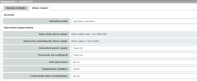
|
Management >> Service I/O >> Alarm output
|
|
General
|
Operating mode
|
Operation supervision / Manual setting
The alarm output can be controlled automatically using Operation supervision (default) or Manual setting.
|
|
|
Manual setting
|
Closed / Open (Alarm)
The desired state of the alarm output (for function control) can be selected here:
If the state is manually set to Open (Alarm), the FAIL LED does not light up red (no alarm).
|
|
Operation Supervision
|
Current state
|
Displays the state of the alarm output.
|
|
|
Redundant power
supply
(Only FL MGUARD 4302)
|
If set to Ignore, the state of the power supply does not influence the alarm output.
If set to Supervise, the alarm output is opened if either of the two supply voltages fails.
|
|
|
Passwords not configured
|
Monitors whether the default administrator passwords for the root and admin users have been changed.
If set to Ignore, the unchanged default passwords do not influence the alarm output.
If set to Supervise, the alarm output is opened if the default passwords have not been changed.
|
|
|
Link supervision
|
Monitoring of the link status of the Ethernet connections.
If set to Ignore, the link status of the Ethernet connections does not influence the alarm output.
If set to Supervise, the alarm output is opened if one link does not indicate connectivity. Set the links to be monitored under MAU Settings in the Link supervision menu.
|
|
|
Temperature condition
|
The alarm output indicates overtemperature and undertemperature. The permissible range is set under "System temperature (°C)" in the Management >> System Settings >> Host menu.
If set to Ignore, the temperature does not influence the signal contact.
If set to Supervise, the alarm output is opened if the temperature is not within the permissible range.
|
|
|
Connectivity state of redundancy
|
Only if the Redundancy function is used (see Section 13).
If set to Ignore, the connectivity check does not influence the alarm output.
If set to Supervise, the alarm output is opened if the connectivity check fails. This is regardless of whether the mGuard is active or in standby mode.
|
4.9Management >> Restart
4.9.1Restart
|
Management >> Restart >> Reboot
|
|
Reboot
|
Reboot
|
Click on the “Reboot” button to restart (reboot) the mGuard.
The device requires approx. 30 seconds to restart.
A restart has the same effect as a temporary interruption to the power supply. The mGuard is switched off and back on again.
A restart is required in the event of an error. It may also be required after a software update.
|