
The firewall redundancy functions are not available on the devices of the FL MGUARD 2000 series.
The firewall redundancy functions are not available on the devices of the FL MGUARD 2000 series. |
There are several different ways of compensating for errors using the mGuard so that an existing connection is not interrupted.
–Firewall redundancy: two identical mGuard devices can be combined to form a redundancy pair, meaning one takes over the functions of the other if an error occurs.
–Ring/network coupling: in ring/network coupling, another method is used. Parts of a network are designed as redundant. In the event of errors, the alternative path is selected.
Using firewall redundancy, it is possible to combine two identical mGuard devices into a redundancy pair pair (single virtual router). One mGuard takes over the functions of the other if an error occurs. Both mGuard devices run synchronously, meaning an existing connection is not interrupted when the device is switched.
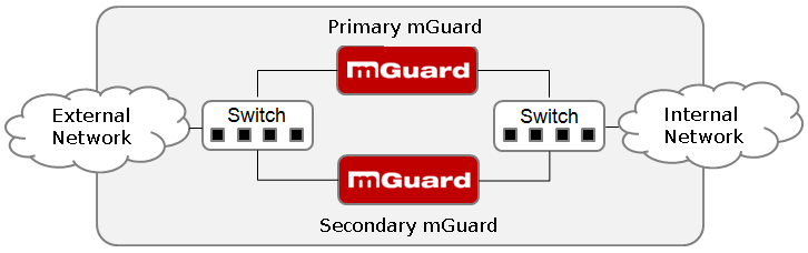
Figure 13-1: Firewall redundancy (example)
Basic requirements for firewall redundancy
–Only identical mGuard devices can be used together in a redundancy pair.
–In Router network mode, firewall redundancy is only supported with “Static” Router mode.
–In Stealth network mode, firewall redundancy is only supported when stealth configuration is set to “Multiple clients”.
–For further restrictions, see “Requirements for firewall redundancy” on page 306 and “Limits of firewall redundancy” on page 315.
13.1.1Components in firewall redundancy
Firewall redundancy is comprised of several components:
–Connectivity check
Checks whether the necessary network connections have been established.
–Availability check
Checks whether an active mGuard is available and whether this should remain active.
–State synchronization of the firewall
The mGuard on standby receives a copy of the current firewall database state.
–Virtual network interface
Provides virtual IP addresses and MAC addresses that can be used by other devices as routes and default gateways.
–State monitoring
Coordinates all components.
–Status indicator
Shows the user the state of the mGuard.
Connectivity check
On each mGuard in a redundancy pair, checks are constantly made as to whether a connection is established via which the network packets can be forwarded.
Each mGuard checks its own internal and external network interfaces independently of each other. Both interfaces are tested for a continuous connection. This connection must be in place, otherwise the connectivity check will fail.
ICMP echo requests can also be sent (optional). The ICMP echo requests can be set via the Redundancy >> Firewall Redundancy >> Connectivity Checks menu.
Availability check
On each mGuard in a redundancy pair, checks are also constantly performed to determine whether an active mGuard is available and whether it should remain active. A variation of the CARP (Common Address Redundancy Protocol) is used here.
The active mGuard constantly sends presence notifications via its internal and external network interface while both mGuard devices listen. If a dedicated Ethernet link for state synchronization of the firewall is available, the presence notification is also sent via this link. In this case, the presence notification for the external network interface can also be suppressed.
The availability check fails if an mGuard does not receive any presence notifications within a certain time. The check also fails if an mGuard receives presence notifications with a lower priority than its own.
The data is always transmitted via the physical network interface and never via the virtual network interface.
State synchronization
The mGuard on standby receives a copy of the state of the mGuard that is currently active.
This includes a database containing the forwarded network connections. This database is filled and updated constantly by the forwarded network packets. The unencryptted data of the state is transmitted via the physical LAN interface and never via the virtual network interface.
NOTE: Unencrypted data transfer The data from the connection tracking table of the firewall of the redundancy pair is transmitted unencrpyted over the LAN network. Use the redundancy function only in a secure network environment where the LAN network is fully under the control of the operator. |
To keep internal data traffic to a minimum, a VLAN can be configured to store the synchronization data in a separate multicast and broadcast domain.
Virtual IP addresses
Each mGuard is configured with virtual IP addresses. The number of virtual IP addresses depends on the network mode used. Both mGuard devices in a redundancy pair must be assigned the same virtual IP addresses. The virtual IP addresses are required by the mGuard to establish virtual network interfaces.
Two virtual IP addresses are required in Router network mode, while others can be created. One virtual IP address is required for the external network interface and the other for the internal network interface.
These IP addresses are used as a gateway for routing devices located in the external or internal LAN. In this way, the devices can benefit from the high availability resulting from the use of both redundant mGuard devices.
The redundancy pair automatically defines MAC addresses for the virtual network interface. These MAC addresses are identical for the redundancy pair. In Router network mode, both mGuard devices share a MAC address for the virtual network interface connected to the external and internal Ethernet segment.
In Router network mode, the mGuard devices support forwarding of special UDP/TCP ports from a virtual IP address to other IP addresses, provided the other IP addresses can be reached by the mGuard. In addition, the mGuard also masks data with virtual IP addresses when masquerading rules are set up.
State monitoring
State monitoring is used to determine whether the mGuard is active, on standby or has an error. Each mGuard determines its own state independently, based on the information provided by other components. State monitoring ensures that two mGuard devices are not active at the same time.
The status indicator contains detailed information on the firewall redundancy state. A summary of the state can be called via the Redundancy >> Firewall Redundancy >> Redundancy or Redundancy >> Firewall Redundancy >> Connectivity Checks menu.
13.1.2Interaction of the firewall redundancy components
During operation, the components work together as follows: both mGuard devices perform ongoing connectivity checks for both of their network interfaces (internal and external). In addition, an ongoing availability check is performed. Each mGuard listens continuously for presence notifications (CARP) and the active mGuard also sends them.
Based on the information from the connectivity and availability checks, the state monitoring function is made aware of the state of the mGuard devices. State monitoring ensures that the active mGuard mirrors its data to the other mGuard (state synchronization).
13.1.3Firewall redundancy settings from previous versions
Existing configuration profiles for firmware Version 6.1.x (and earlier) can be imported with certain restrictions. For more information, please contact Phoenix Contact.
13.1.4Requirements for firewall redundancy
–To use the redundancy function, both mGuard devices must have the same firmware.
–Each set of targets for the connectivity check can contain more than ten targets. (A fail-over time cannot be guaranteed without an upper limit.)
Redundancy >> Firewall Redundancy >> Redundancy
–>> External Interface >> Primary External Targets (for ICMP echo requests)
–>> External Interface >> Secondary External Targets (for ICMP echo requests)
–>> Internal Interface >> Primary External Targets (for ICMP echo requests)
–>> Internal Interface >> Secondary External Targets (for ICMP echo requests)
If “at least one target must respond” or “all targets of one set must respond” is selected under External Interface >> Kind of check, then External Interface >> Primary External Targets (for ICMP echo requests) must not be empty. This also applies to the internal interface.
–In Router network mode, at least one external and one internal virtual IP address must be set. A virtual IP address cannot be listed twice.
13.1.5Fail-over switching time
The mGuard calculates the intervals for the connectivity check and availability check automatically according to the variables under Fail-over switching time.
Connectivity check
The factors which define the intervals for the connectivity check are specified in Table 13-1.
64 byte ICMP echo requests are sent for the connectivity check. They are sent on Layer 3 of the Internet protocol. When VLAN is not used, 18 bytes for the MAC header and checksum are added to this with Ethernet on Layer 2. The ICMP echo reply is the same size.
The bandwidth is also shown in Table 13-1. This takes into account the values specified for a single target and adds up the bytes for the ICMP echo request and reply.
The timeout on the mGuard following transmission includes the following:
–The time required by the mGuard to transmit an ICMP echo reply. If other data traffic is expected, half duplex mode is not suitable here.
–The time required for the transmission of the ICMP echo request to a target. Consider the latency during periods of high capacity utilization. This applies especially when routers forward the request. The actual latency may be twice the value of the configured latency in unfavorable circumstances (connectivity check error).
–The time required on each target for processing the request and transmitting the reply to the Ethernet layer. Please note that full duplex mode is also used here.
–The time for transmission of the ICMP echo reply to the mGuard.
If secondary targets are configured, then additional ICMP echo requests may occasionally be sent to these targets. This must be taken into account when calculating the ICMP echo request rate.
The timeout for a single ICMP echo request is displayed in Table 13-1. This does not indicate how many of the responses can be missed before the connectivity check fails. The check tolerates a negative result for one of two back-to-back intervals.
Availability check
Presence notifications (CARP) are up to 76 bytes in size on Layer 3 of the Internet protocol. When VLAN is not used, 18 bytes for the MAC header and checksum are added to this with Ethernet on Layer 2. The ICMP echo reply is the same size.
Table 13-2 shows the maximum frequency at which the presence notifications (CARP) are sent from the active mGuard. It also shows the bandwidth used in the process. The frequency depends on the mGuard priority and the Fail-over switching time .
Table 13-2 also shows the maximum latency tolerated by the mGuard for the network that is used to transmit the presence notifications (CARP). If this latency is exceeded, the redundancy pair can exhibit undefined behavior.
13.1.6Error compensation through firewall redundancy
Firewall redundancy is used to compensate for hardware failures.
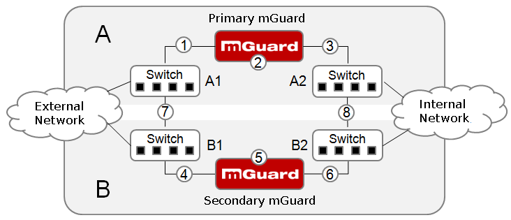
Figure 13-2: Possible error locations (1 ... 8)
Figure 13-2 shows a diagram containing various error locations (not related to the network mode).
Each of the mGuard devices in a redundancy pair is located in a different area (A and B). The mGuard in area A is connected to switch A1 through its external Ethernet interface and to switch A2 through its internal Ethernet interface. mGuard B is connected accordingly to switches B1 and B2. In this way, the switches and mGuard devices connect an external Ethernet network to an internal Ethernet network. The connection is established by forwarding network packets (in Router network mode).
Firewall redundancy compensates for errors shown in Figure 13-2 if only one occurs at any given time. If two errors occur simultaneously, they are only compensated if they occur in the same area (A or B).
For example, if one of the mGuard devices fails completely due to a power outage, then this is detected. A connection failure is compensated if the connection fails completely or partially. When the connectivity check is set correctly, a faulty connection caused by the loss of data packets or an excessive latency is detected and compensated. Without the connectivity check, the mGuard cannot determine which area caused the error.
A connection failure between switches on a network side (internal/external) is not compensated for (7 and 8 in Figure 13-2).
13.1.7Handling firewall redundancy in extreme situations
The situations described here only occur rarely. |
Restoration in the event of a network lobotomy
A network lobotomy occurs if a redundancy pair is separated into two mGuard devices operating independently of one another. In this case, each mGuard deals with its own tracking information as the two mGuard devices can no longer communicate via Layer 2. A network lobotomy can be triggered by a rare and unfortunate combination of network settings, network failures, and firewall redundancy settings.
Each mGuard is active during a network lobotomy. The following occurs after the network lobotomy has been rectified: if the mGuard devices have different priorities, the device with the higher priority becomes active and the other switches to standby mode. If both mGuard devices have the same priority, an identifier sent with the presence notifications (CARP) determines which mGuard becomes active.
Both mGuard devices manage their own firewall state during the network lobotomy. The active mGuard retains its state. Connections on the other mGuard, which were established during the lobotomy, are dropped.
Fail-over when establishing complex connections
Complex connections are network protocols which are based on different IP connections. One example of this is the FTP protocol. In the case of FTP, the client establishes a control channel for a TCP connection. The server is then expected to open another TCP connection over which the client can then transmit data. The data channel on port 20 of the server is set up while the control channel on port 21 of the server is being established.
If the relevant connection tracking function is activated on the mGuard (see “Advanced” on page 200), complex connections of this type are tracked. In this case, the administrator only needs to create a firewall rule on the mGuard which allows the client to establish a control channel to the FTP server. The mGuard enables the server to establish a data channel automatically, regardless of whether the firewall rules allow for this.
The tracking of complex connections is part of the firewall state synchronization process. However, to keep the latency short, the mGuard forwards the network packets independently of the firewall state synchronization update that has been triggered by the network packets themselves.
Therefore, it may be the case for a very brief period that a state change for the complex connection is not forwarded to the mGuard on standby if the active mGuard fails. In this case, tracking of the connection from the mGuard which is active after the fail-over is not continued correctly. This cannot be corrected by the mGuard. The data link is then reset or interrupted.
Fail-over when establishing semi-unidirectional connections
A semi-unidirectional connection refers to a single IP connection (such as UDP connections) where the data only travels in one direction after the connection is established with a bidirectional handshake.
The data flows from the responder to the initiator. The initiator only sends data packets at the very start.
The following applies only to certain protocols which are based on UDP. Data always flows in both directions on TCP connections.
If the firewall of the mGuard is set up to only accept data packets from the initiator, the firewall accepts all related responses per se. This happens regardless of whether or not a relevant firewall rule is available.
A scenario is conceivable in which the mGuard allows the initiating data packet to pass through and then fails before the relevant connection entry has been made in the other mGuard. The other mGuard may then reject the responses as soon as it becomes the active mGuard.
The mGuard cannot correct this situation due to the single-sided connection. As a countermeasure, the firewall can be configured so that the connection can be established in both directions. This is normally already handled via the protocol layer and no additional assignment is required.
Loss of data packets during state synchronization
If data packets are lost during state synchronization, this is detected automatically by the mGuard, which then requests the active mGuard to send the data again.
This request must be answered within a certain time, otherwise the mGuard on standby is assigned the “outdated” state and asks the active mGuard for a complete copy of all state information.
The response time is calculated automatically from the fail-over switching time. This is longer than the time for presence notifications (CARP), but shorter than the upper limit of the fail-over switching time.
Loss of presence notifications (CARP) during transmission
A one-off loss of presence notifications (CARP) is tolerated by the mGuard, but it does not tolerate the loss of subsequent presence notifications (CARP). This applies to the availability check on each individual network interface, even when these are checked simultaneously. It is therefore very unlikely that the availability check will fail as a result of a very brief network interruption.
Loss of ICMP echo requests/replies during transmission
ICMP echo requests or replies are important for the connectivity check. Losses are always observed, but are tolerated under certain circumstances.
The following measures can be used to increase the tolerance level for ICMP echo requests.
–Select at least one target must respond under Kind of check in the Redundancy >> Firewall Redundancy >> Connectivity Checks menu.
–Also define a secondary set of targets here. The tolerance level for the loss of ICMP echo requests can be further increased by entering the targets of unreliable connections under both sets (primary and secondary) or listing them several times within a set.
Restoring the primary mGuard following a failure
If a redundancy pair is defined with different priorities, the secondary mGuard becomes active if the connection fails. The primary mGuard becomes active again after the failure has been rectified. The secondary mGuard receives a presence notification (CARP) and returns to standby mode.
State synchronization
If the primary mGuard becomes active again after a failure of the internal network connection, it may contain an obsolete copy of the firewall database. This database must, therefore, be updated before the connection is reestablished. The primary mGuard ensures that it receives an up-to-date copy before becoming active.
13.1.8Interaction with other devices
Virtual and real IP addresses
With firewall redundancy in Router network mode, the mGuard uses real IP addresses to communicate with other network devices.
Virtual IP addresses are used in the following two cases:
–Virtual IP addresses are used when establishing and operating VPN connections.
–If DNS and NTP services are used according to the configuration, they are offered to internal virtual IP addresses.
The use of real (management) IP addresses is especially important for the connectivity check and availability check. Therefore, the real (management) IP address must be configured so that the mGuard can establish the required connections.
The following are examples of how and why mGuard communication takes place:
–Communication with NTP servers to synchronize the time
–Communication with DNS servers to resolve host names (especially those from VPN partners)
–To register its IP address with a DynDNS service
–To send SNMP traps
–To forward log messages to a SysLog server
–To download a CRL from an HTTP(S) server
–To authenticate a user via a RADIUS server
–To download a configuration profile via an HTTPS server
–To download a firmware update from an HTTPS server
With firewall redundancy in Router network mode, devices connected to the same LAN segment as the redundancy pair must use their respective virtual IP addresses as gateways for their routes. If these devices were to use the actual IP address of either of the mGuard devices, this would work until that particular mGuard failed. However, the other mGuard would then not be able to take over.
Targets for the connectivity check
If a target is set for ICMP echo requests as part of the connectivity check, these requests must be answered within a certain time, even if the network is busy with other data. The network path between the redundancy pair and these targets must be set so that it is also able to forward the ICMP responses when under heavy load. Otherwise, the connectivity check for an mGuard could erroneously fail.
Targets can be configured for the internal and external interface in the connectivity check (see “Connectivity Checks” on page 289). It is important that these targets are actually connected to the specified interface. An ICMP echo reply cannot be received by an external interface when the target is connected to the internal interface (and vice versa). When the static routes are changed, it is easy to forget to adjust the configuration of the targets accordingly.
The targets for the connectivity check should be well thought out. Without a connectivity check, all it takes are two errors for a network lobotomy to occur.
A network lobotomy is prevented if the targets for both mGuard devices are identical and all targets have to answer the request. However, the disadvantage of this method is that the connectivity check fails more often if one of the targets does not offer high availability.
In Router network mode, we recommend defining a high-availability device as the target on the external interface. This can be the default gateway for the redundancy pair (e.g., a virtual router comprised of two independent devices). In this case, either no targets or a selection of targets should be defined on the internal interface.
Please also note the following information when using a virtual router consisting of two independent devices as the default gateway for a redundancy pair. If these devices use VRRP to synchronize their virtual IP, then a network lobotomy could split the virtual IP of this router into two identical copies. These routers could use a dynamic routing protocol and only one may be selected for the data flows of the network being monitored by the mGuard. Only this router should keep the virtual IP. Otherwise, you can define targets which are accessible via this route in the connectivity check. In this case, the virtual IP address of the router would not be a sensible target.
Redundancy group
Several redundancy pairs can be connected within a LAN segment (redundancy group). You define a value as an identifier (using the router ID) for each virtual instance of the redundancy pair. As long as these identifiers are different, the redundancy pairs do not come into conflict with each other.
Data traffic
In the event of a high latency in a network used for state synchronization updates or a serious data loss on this network, the mGuard on standby is assigned the “outdated” state. This does not occur, however, as long as no more than two back-to-back updates are lost. This is because the mGuard on standby automatically requests a repeat of the update. The latency requirements are the same as those detailed under “Fail-over switching time” on page 307.
Sufficient bandwidth
The data traffic generated as a result of the connectivity check, availability check, and state synchronization uses bandwidth in the network. The connectivity check also generates complicated calculations. There are several ways to limit this or stop it completely.
If the impact on other devices is unacceptable:
–The connectivity check must either be deactivated, or must only relate to the actual IP address of the other mGuard.
–The data traffic generated by the availability check and state synchronization must be moved to a separate VLAN.
–Switches must be used which allow separation of the VLANs.
13.1.9Limits of firewall redundancy
–In Router network mode, firewall redundancy is only supported with “Static” mode.
–Access to the mGuard via the HTTPS, SNMP, and SSH management protocols is only possible with a real IP address from each mGuard. Attempts to access virtual addresses are rejected.
–The following features cannot be used with firewall redundancy.
–A DHCP server
–A DHCP relay
–A user firewall
–The redundancy pair must have the same configuration. Take this into account when making the following settings:
–NAT settings (masquerading, port forwarding, and 1:1 NAT)
–Flood protection
–Packet filter (firewall rules, MAC filter, advanced settings)
–Some network connections may be interrupted following a network lobotomy. (See “Restoration in the event of a network lobotomy” on page 310.)
–After a fail-over, semi-unidirectional or complex connections that were established in the second before the fail-over may be interrupted. (See “Fail-over when establishing complex connections” on page 310 and “Fail-over when establishing semi-unidirectional connections” on page 310.)
–State synchronization does not replicate the connection tracking entries for ICMP echo requests forwarded by the mGuard. Therefore, ICMP echo replies can be dropped according to the firewall rules if they only reach the mGuard after the fail-over is completed. Please note that ICMP echo replies are not suitable for measuring the fail-over switching time.
–Masquerading involves hiding the transmitter behind the first virtual IP address or the first internal IP address. This is different to masquerading on the mGuard without firewall redundancy. When firewall redundancy is not activated, the external or internal IP address hiding the transmitter is specified in a routing table.
1Bidirectional includes traffic in both directions. For example, 1500 Mbps means that 750 Mbps is forwarded in each direction. |

