Devices of the new device generation are configured with the following default settings: Network mode "Router", Router mode "DHCP".
The mGuard has the following interfaces with external access:
Device |
Ethernet: –internal: LAN (Ports: XF2-4 or XF2-5) –external: WAN (Port: XF1) –DMZ: DMZ (Port: XF5) |
FL MGUARD 2102 |
LAN: 1 |
FL MGUARD 4302 |
LAN: 1 |
FL MGUARD 2105 |
LAN: 4 |
FL MGUARD 4305 |
LAN: 3 |
FL MGUARD 4102 PCI(E) |
LAN: 1 |
The LAN port is connected to a stand-alone computer or the local network (internal). The WAN port is used to connect to the external network.
Network ports (Migration mGuard 8 --> mGuard 10)
mGuard 8 |
mGuard 10 |
mGuard 8 (Intern mit eingebautem Switch) |
mGuard 10 (Intern mit eingebautem Switch) |
|---|---|---|---|
FL MGUARD 2000/4000 |
|||
WAN |
XF1 |
(n/a) |
(n/a) |
LAN1 |
XF2 |
swp2 |
swp0 |
FL MGUARD 2105/4305 |
|||
LAN2 |
XF3 |
swp0 |
swp1 |
LAN3 |
XF4 |
swp1 |
swp2 |
FL MGUARD 2105 |
|||
LAN4 |
XF5 |
swp3 |
swp3 |
FL MGUARD 4305 |
|||
DMZ |
XF5 |
swp4 |
dmz0 |
Nicht bei FL MGUARD 2105/FL MGUARD 4305 |
|||
LAN5 |
(n/a) |
swp4 |
(n/a) |
Connecting the network interface
The mGuard platforms have DTE interfaces. Connect the mGuards to the DTE interface using an Ethernet crossover cable. Here auto MDIX is permanently switched on, so it does not matter if the auto negotiation parameter is disabled.
MAC addresses
The MAC address of the WAN interface determined by the manufacturer is indicated on the type label of the device. The other MAC addresses (LAN/DMZ [optional]) can be calculated as follows:
–WAN interface: see type label.
–LAN interface: MAC address of the WAN interface incremented by 1 (WAN + 1).
Devices with integrated switch: all switch ports use the same MAC address.
–DMZ interface: MAC address of the WAN interface incremented by 4 (WAN + 4).
Example:
–WAN: 00:a0:45:eb:28:9d
–LAN: 00:a0:45:eb:28:9e
–DMZ: 00:a0:45:eb:28:a1
5.1.1Overview of "Router" network mode
Devices of the new device generation are configured with the following default settings: Network mode "Router", Router mode "DHCP". |
If the mGuard is in Router mode, it acts as the gateway between various subnetworks and has both an external interface (WAN port) and an internal interface (LAN port) with at least one IP address.
WAN port
The mGuard is connected to the Internet or other “external” parts of the LAN via its WAN port.
LAN port
The mGuard is connected to a local network or a stand-alone computer via its LAN port.
As in the other modes, firewall and VPN security functions are available (depending on the device).
If the mGuard is operated in Router mode, it must be set as the default gateway on the locally connected computers. This means that the IP address of the mGuard LAN port must be specified as the default gateway address on these computers. |
NAT should be activated if the mGuard is operated in Router mode and establishes the connection to the Internet (see "Network >> NAT" on page 130). Only then can the computers in the connected local network access the Internet via the mGuard. If NAT is not activated, it is possible that only VPN connections can be used. |
There are two router modes:
–Static
–DHCP
The external IP-settings are fixed.
The external IP-settings are requested by the mGuard and assigned by an external DHCP server.
5.1.2Overview of "Stealth" network mode
Stealth mode (Plug-n-Protect) is used to protect a stand-alone computer or a local network with the mGuard. Important: if the mGuard is in Stealth network mode, it is inserted into the existing network (see figure) without changing the existing network configuration of the connected devices.
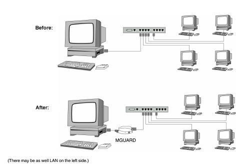
The mGuard analyzes the network traffic and independently configures its network connection accordingly. It works transparently and therefore cannot be detected in the network without configured management IP address. Connected computers keep their network configuration and must not be reconfigured.
As in the other modes, firewall and VPN security functions are available (depending on the device).
Externally supplied DHCP data is allowed through to the connected computer.
In Single-Stealth mode, a firewall installed on the computer must be configured to allow ICMP echo requests (ping), if the mGuard is to provide services such as VPN, DNS, NTP, etc. |
In Stealth mode, the mGuard uses internal IP address 1.1.1.1. This can be accessed from the computer if the default gateway configured on the computer is accessible. |
In the Stealth configurations "Autodetect" and "Static", it is not possible to establish a VPN-connection originating from the internal client through the mGuard. |
Stealth configurations
Autodetect
The mGuard analyzes the outgoing network traffic and independently configures its network connection accordingly. It operates transparently.
For the use of certain functions (e.g. automatic updates or establishment of VPN-connections), it is required that the mGuard makes its own requests of external servers, even in stealth mode. These requests are only possible when the locally connected computer permits ping requests. Configure its security settings accordingly. |
Static
If the mGuard cannot analyze the network traffic, e.g., because the locally connected computer only receives data and does not send it, then Stealth configuration must be set to Static. In this case, further input fields are available for Static Stealth Configuration.
Multiple clients
As with Autodetect, but it is possible to connect more than one computer to the LAN port (secure port) of the mGuard, meaning that multiple IP addresses can be used at the LAN port (secure port) of the mGuard.
For the further configuration of Stealth network mode, see "Stealth" on page 121.
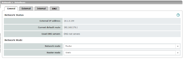
Network Status |
External IP address |
Display only: the addresses via which the mGuard can be accessed by devices from the external network. They form the interface to other parts of the LAN or to the Internet. If the transition to the Internet takes place here, the IP addresses are usually assigned by the Internet service provider (ISP). If an IP address is assigned dynamically to the mGuard, the currently valid IP address can be found here. In Stealth mode, the mGuard adopts the address of the locally connected computer as its external IP. |
|
Current default route |
Display only: the IP address that the mGuard uses to try to reach unknown networks is displayed here. If a default route has not been specified, the field is left empty. |
|
Used DNS servers |
Display only: the names of the DNS servers used by the mGuard for name resolution are displayed here. This information can be useful, for example, if the mGuard is using the DNS servers assigned to it by the Internet service provider. |
Network mode |
Network mode |
Router / Stealth The mGuard must be set to the network mode that corresponds to its connection to the network 
. See also: "Overview of "Router" network mode" on page 111 and "Overview of "Stealth" network mode" on page 112. |
|
Depending on the network mode selected and the mGuard device, different setting options are available on the web interface: |
|
|
Router Mode (Only if "Router" network mode was selected) |
Static / DHCP For a detailed description, see: |
|
(Only if "Stealth" network mode was selected) |
Autodetect / Static / Multiple clients Autodetect The mGuard analyzes the network traffic and independently configures its network connection accordingly. It operates transparently. 
Static If the mGuard cannot analyze the network traffic, e.g., because the locally connected computer only receives data and does not send it, then Stealth configuration must be set to Static. In this case, further input fields are available for Static Stealth Configuration at the bottom of the page. Multiple clients (Default) As with Autodetect, but it is possible to connect more than one computer to the LAN port (secure port) of the mGuard, meaning that multiple IP addresses can be used at the LAN port (secure port) of the mGuard. |
|
||
|
||
|
||
|
Autodetect: ignore NetBIOS over TCP traffic on TCP port 139 (Only with Autodetect Stealth configuration) |
If a Windows computer has more than one network card installed, it may alternate between the different IP addresses for the sender address in the data packets it sends. This applies to network packets that the computer sends to TCP port 139 (NetBIOS). As the mGuard determines the address of the computer from the sender address (and therefore the address via which the mGuard can be accessed), the mGuard would have to switch back and forth, and this would hinder operation considerably. To avoid this, activate the function if the mGuard has been connected to a computer that has these properties. |
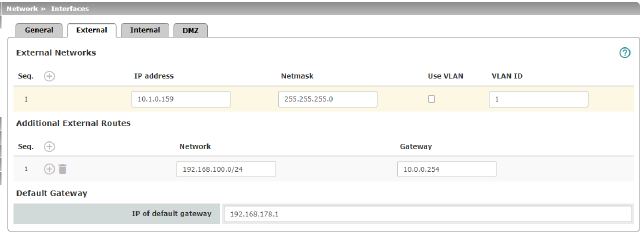
Network >> Interfaces >> External (network mode = "Router", router mode = "Static") |
||
|---|---|---|
The addresses via which the mGuard can be accessed by external devices that are located behind the WAN port. If the transition to the Internet takes place here, the external IP address of the mGuard is assigned by the Internet service provider (ISP). |
||
|
IP address |
IP address via which the mGuard can be accessed via its WAN port. |
|
Netmask |
The netmask of the network connected to the WAN port. |
|
Use VLAN |
If the IP address should be within a VLAN, activate the function. |
|
VLAN ID |
–A VLAN ID between 1 and 4095. –For an explanation of the term "VLAN", please refer to the glossary on page 324. –If you want to delete entries from the list, please note that the first entry cannot be deleted. |
|
OSPF area (Only if OSPF is activated) |
Links the learned (DHCP) or configured (static) addresses/routes of the external network interface to an OSPF area (see "Network >> Dynamic Routing" on page 151). |
In addition to the default route via the default gateway specified below, additional external routes can be specified. |
||
|
Network |
Specify the network in CIDR format (see "CIDR (Classless Inter-Domain Routing)" on page 34). |
|
Gateway |
The gateway via which this network can be accessed. See also "Network example diagram" on page 35. |
Default gateway |
The IP address of a device in the local network (connected to the LAN port) or the IP address of a device in the external network (connected to the WAN port) can be specified here. If the mGuard is used within the LAN, the IP address of the default gateway is assigned by the network administrator. 
|
|
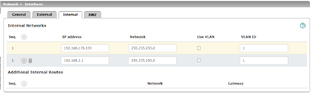
IP address |
IP address under which the mGuard device shall be accessible from the locally connected network via its LAN port. The default settings in Router mode are as follows: –IP address: 192.168.1.1 –Netmask: 255.255.255.0 You can also specify other addresses via which the mGuard can be accessed by devices in the locally connected network. For example, this can be useful if the locally connected network is divided into subnetworks. Multiple devices in different subnetworks can then access the mGuard via different addresses. |
|
|
Netmask |
The netmask of the network connected to the LAN port. |
|
Use VLAN |
If the IP address should be within a VLAN, activate the function. |
|
–A VLAN ID between 1 and 4095. –For an explanation of the term "VLAN", please refer to the glossary on page 324. –If you want to delete entries from the list, please note that the first entry cannot be deleted. |
|
|
OSPF area (Only if OSPF is activated) |
Links the static addresses/routes of the internal network interface to an OSPF area (see "Network >> Dynamic Routing" on page 151). |
Additional Internal Routes |
Additional routes can be defined if further subnetworks are connected to the locally connected network. |
|
|
Network |
Specify the network in CIDR format (see "CIDR (Classless Inter-Domain Routing)" on page 34). |
|
The gateway via which this network can be accessed. See also "Network example diagram" on page 35. |
|
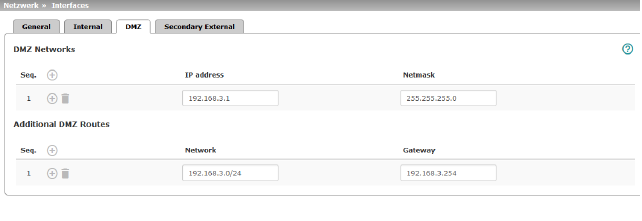
Network >> Interfaces >> DMZ (Network mode = "Router") |
||
|---|---|---|
|
(Only for FL MGUARD 4305) |
IP addresses |
IP address via which the mGuard can be accessed by devices in the network connected to the DMZ port. 
In "Router" network mode, every newly added table line has default settings: –IP address: 192.168.3.1 –Netmask: 255.255.255.0 You can also specify other addresses via which the mGuard can be accessed by devices in the networks connected to the DMZ port. For example, this can be useful if the network connected to the DMZ port is divided into subnetworks. Multiple devices in different subnetworks can then access the mGuard via different addresses. |
|
IP address |
IP address via which the mGuard can be accessed via its DMZ port. Default: 192.168.3.1 |
|
Netmask |
The netmask of the network connected to the DMZ port. Default: 255.255.255.0 |
|
OSPF area (Only if OSPF is activated) |
Links the static addresses/routes of the DMZ network interface to an OSPF area (see "Network >> Dynamic Routing" on page 151). |
Additional DMZ Routes |
Additional routes can be defined if further subnetworks are connected to the DMZ. |
|
|
Network |
Specify the network in CIDR format (see "CIDR (Classless Inter-Domain Routing)" on page 34). Default: 192.168.3.0/24 |
|
Gateway |
The gateway via which this network can be accessed. See also "Network example diagram" on page 35. Default: 192.168.3.254 |
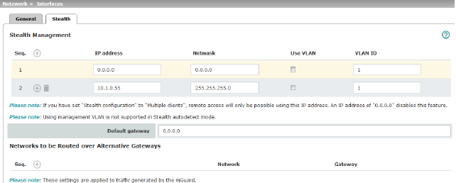
Additional Management IP addresses for the administration of the mGuard can be specified here. If: –The Multiple clients option is selected under Stealth configuration –The client does not answer ARP requests –No client is available Remote access via HTTPS, SNMP, and SSH is only possible using this address. 
|
||
|
Management IP address via which the mGuard can be accessed and administered. 
The IP address "0.0.0.0" deactivates the management IP address. Change the management IP address first before specifying any additional addresses. |
|
|
Netmask |
The netmask of the IP address above. |
|
Use VLAN |
This option is valid only if you have set the „Stealth configuration“ option to „Multiple clients“. IP address and netmask of the VLAN port. If the IP address should be within a VLAN, activate the function. |
|
VLAN ID |
This option only applies if you set the "Stealth configuration" option to "Multiple clients". –A VLAN ID between 1 and 4095. –An explanation can be found under "VLAN" on page 324. –If you want to delete entries from the list, please note that the first entry cannot be deleted. 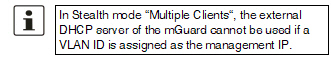
|
|
The default gateway of the network where the mGuard is located. 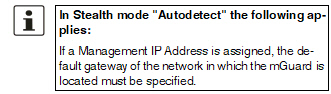
|
|
Networks to be routed over alternative gateways |
In Stealth modes "Autodetect" and "Static", the mGuard adopts the default gateway of the computer connected to its LAN port. This does not apply if a management IP address is configured with the default gateway. Alternative routes can be specified for data packets destined for the WAN that have been created by the mGuard. These include for instance the packets from the following types of data traffic: –Download of certificate revocation lists (CRLs) –Download of a new configuration –Communication with an NTP server (for time synchronization) –Sending and receiving encrypted data packets from VPN connections –Requests to DNS servers –Log messages –Download of firmware updates –Download of configuration profiles from a central server (if configured) –SNMP traps |
|
|
If this option is used, make the relevant entries afterwards. If it is not used, the affected data packets are routed via the default gateway specified for the client. 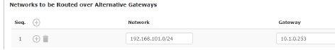
|
|
|
Network |
Specify the network in CIDR format (see "CIDR (Classless Inter-Domain Routing)" on page 34). |
|
Gateway |
The gateway via which this network can be accessed. The routes specified here are mandatory routes for data packets created by the mGuard. This setting has priority over other settings (see also "Network example diagram" on page 35). |
Settings for Stealth mode (static) |
Client IP address |
The IP address of the computer connected to the LAN port. |
|
The physical address of the network card of the local computer to which the mGuard is connected. •The MAC address can be determined as follows: In DOS (Start, All Programs, Accessories, Command Prompt), enter the following command: ipconfig /all |
|
|
|
The MAC address does not necessarily have to be specified. The mGuard can automatically obtain the MAC address from the client. The MAC address 0:0:0:0:0:0 must be set in order to do this. Please note that the mGuard can only forward network packets to the client once the MAC address of the client has been determined. If no Stealth Management IP Address or Client MAC address is configured in static Stealth mode, then DAD ARP requests are sent via the internal interface (see RFC 2131, "Dynamic Host Configuration Protocol", Section 4.4.1). |
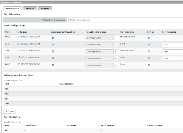
Network >> Ethernet >> MAU Settings |
||
|---|---|---|
|
(Only for FL MGUARD 4305) |
Port mirroring receiver |
The integrated switch controls port mirroring in order to monitor the network traffic. Here, you can decide which ports you want to monitor. The switch then sends copies of data frames from the monitored ports to a selected port. The port mirroring function enables any frames to be forwarded to a specific recipient. You can select the receiver port or the mirroring of the incoming and outgoing frames from each switch port. |
MAU Configuration |
Configuration and status indication of the Ethernet connections: |
|
|
Port |
Name of the Ethernet connection to which the row refers. |
|
Media type |
Media type of the Ethernet connection. |
|
Automatic configuration |
Activated: tries to determine the required operating mode automatically. Deactivated: uses the operating mode specified in the “Manual configuration” column. |
|
Manual configuration |
The desired operating mode when Automatic configuration is deactivated. |
|
Current mode |
The current operating mode of the network connection. |
|
Port on
|
Switches the Ethernet connection on or off. |
|
Only visible when the "Management >> Service I/O >> Alarm output" menu item „Link supervision“ is set to “Supervise”. If link supervision is active, the alarm output is opened if one link does not indicate connectivity. |
|
|
Port mirroring (Only for FL MGUARD 4305) |
The port mirroring function enables any frames to be forwarded to a specific recipient. You can select the receiver port or the mirroring of the incoming and outgoing frames from each switch port. |
Address Resolution Table (Only for FL MGUARD 4305)
|
Port |
Name of the Ethernet connection to which the row refers. |
MAC addresses |
Lists the MAC addresses of the connected Ethernet-capable devices. The switch can learn MAC addresses which belong to the ports of its connected Ethernet-capable devices. The contents of the list can be deleted by clicking on the “Purge” button. |
|
Port Statistics (Only for FL MGUARD 4305)
|
A statistic is displayed for each physically accessible port of the integrated Managed Switch. The counter can be reset via the web interface or the following command: /Packages/mguard-api_0/mbin/action switch/reset-phy-counters |
|
|
Port |
Name of the Ethernet connection to which the row refers. |
|
TX collisions |
Number of errors while sending the data |
|
TX octets |
Data volume sent |
|
Number of received frames with invalid checksum |
|
|
RX good octets |
Volume of the valid data received |
Only available with FL MGUARD 4305. |
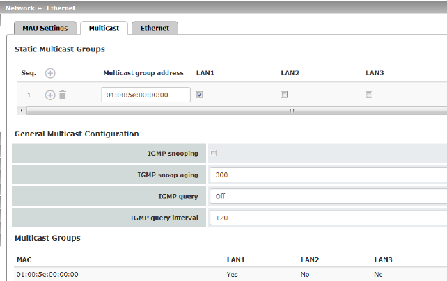
Network >> Ethernet >> Multicast |
||
|---|---|---|
Static Multicast Groups |
Static Multicast Groups |
Note: For data to be correctly forwarded to the configured ports in Static Multicast Groups, "IGMP snooping" must be enabled (see below). Multicast is a technology which enables data to be sent to a group of recipients, without the transmitter having to send it multiple times. The data replication takes place through the distributor within the network. You can create a list of multicast group addresses. The data is forwarded to the configured ports (XF2 ... XF4). |
General Multicast Configuration |
(Not active in network mode „Stealth“) |
The switch uses IGMP snooping to guarantee that multicast data is only forwarded via ports which are intended for this use. |
|
IGMP snoop aging |
Period, after which membership to the multicast group expires, in seconds. |
|
IGMP query |
IGMP is used to join and leave a multicast group. Here, the IGMP version can be selected. IGMP version v1 (IGMPv1) is no longer supported. All devices of the new device generation exclusively support IGMP version v2 (IGMPv2). |
|
IGMP query interval |
Interval in which IGMP queries are generated in seconds. If the interval is changed, new IGMP requests are generated only after the previously configured interval has expired. |
Multicast Groups |
Displays the multicast groups. The display contains all static entries and the dynamic entries which are discovered by IGMP snooping. |
|
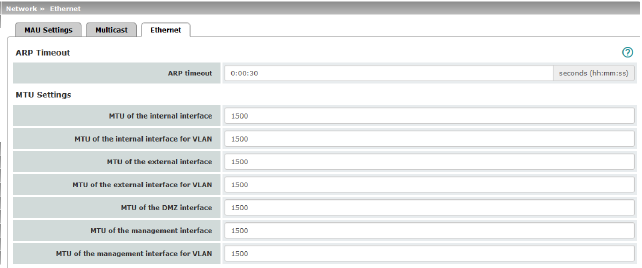
Network >> Ethernet >> Ethernet |
||
|---|---|---|
ARP Timeout |
ARP Timeout |
Service life of entries in the ARP table. The entry can be in seconds [ss], minutes and seconds [mm:ss] or hours, minutes, and seconds [hh:mm:ss]. MAC and IP addresses are assigned to each other in the ARP table. |
The MTU settings |
MTU of the ... interface |
The maximum transfer unit (MTU) defines the maximum IP packet length that may be used for the relevant interface. Allowed values: 68 - 1500 The following applies for a VLAN interface: 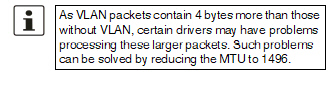
|
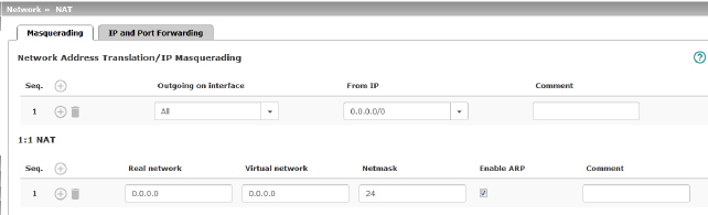
Network >> NAT >> Masquerading |
||
|---|---|---|
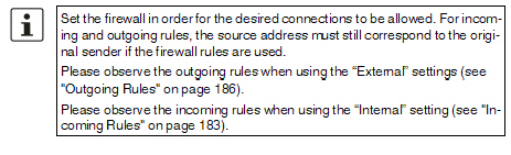
Lists the rules established for NAT (Network Address Translation). For outgoing data packets, the device can rewrite the specified sender IP addresses from its internal network to its own external address, a technique referred to as NAT (Network Address Translation), see also NAT (Network Address Translation) in the glossary. This method is used if the internal addresses cannot or should not be routed externally, e.g., because a private address area such as 192.168.x.x or the internal network structure should be hidden. The method can also be used to hide external network structures from the internal devices. To do so, set the Internal option under Outgoing on interface . The Internal setting allows for communication between two separate IP networks where the IP devices have not configured a (useful) default route or differentiated routing settings (e.g., PLCs without the corresponding settings). The corresponding settings must be made under 1:1 NAT . This method is also referred to as IP masquerading. |
||
|
Default setting: IP Masquerading is active for packets routed from the internal network (LAN) to the external network (WAN) (LAN --> WAN). 

|
|
|
Internal / External / DMZ / All external Specifies via which interface the data packets are sent so that the rule applies to them. „All external“ refers to "External" for FL MGUARD 2000/4000 devices. |
|
|
|
Masquerading is defined, which applies for network data flows in Router mode. These data flows are initiated so that they lead to a destination device which can be accessed over the selected network interface on the mGuard. |
|
|
To do this, the mGuard replaces the IP address of the initiator with a suitable IP address of the selected network interface in all associated data packets. The effect is the same as for the other values of the same variables. The IP address of the initiator is hidden from the destination of the data flow. In particular, the destination does not require any routes in order to respond in a data flow of this type (not even a default route (default gateway)). |
|
|
|
|
From IP |
0.0.0.0/0 means that all internal IP addresses are subject to the NAT procedure. To specify an address area, use CIDR format (see "CIDR (Classless Inter-Domain Routing)" on page 34). Name of IP groups, if defined. When a name is specified for an IP group, the host names, IP addresses, IP areas or networks saved under this name are taken into consideration (see "IP/Port Groups" on page 198). 
|
|
Can be filled with appropriate comments. |
|
|
|
Lists the rules established for 1:1 NAT (Network Address Translation). With 1:1 NAT, the sender IP addresses are exchanged so that each individual address is exchanged with another specific address, and is not exchanged with the same address for all data packets, as in IP masquerading. This enables the mGuard to mirror addresses from the real network to the virtual network. |
|
Example: |
The mGuard is connected to network 192.168.0.0/24 via its LAN port and to network 10.0.0.0/24 via its WAN port. By using 1:1 NAT, the LAN computer with IP address 192.168.0.8 can be accessed via IP address 10.0.0.8 in the virtual network. 
|
|
|
The mGuard claims the IP addresses entered for the “Virtual network” for the devices in its “Real network”. The mGuard returns ARP answers for all addresses from the specified “Virtual network” on behalf of the devices in the “Real network”. The IP addresses entered under “Virtual network” must not be used. They must not be assigned to other devices or used in any way, as an IP address conflict would otherwise occur in the virtual network. This even applies when no device exists in the “Real network” for one or more IP addresses from the specified “Virtual network”. |
|
|
Default setting: 1:1 NAT is not active. 
|
|
|
Real network |
The real IP address of the client that should be reachable from another network via the virtual IP address (depending on the scenario at LAN, WAN, or DMZ port). One or more clients can be reachable depending on the network mask. 1:1-NAT is possible between all interfaces (LAN <–> WAN, LAN <–> DMZ, DMZ <–> WAN). |
|
Virtual network |
The virtual IP address with which the clients are reachable from the other network (depending on the scenario at LAN, WAN, or DMZ port). 
1:1-NAT is possible between all interfaces (LAN <–> WAN, LAN <–> DMZ, DMZ <–> WAN). |
|
Netmask |
The netmask as a value between 1 and 32 for the local and external network address (see also "CIDR (Classless Inter-Domain Routing)" on page 34). |
|
Enable ARP |
When the function is activated, ARP requests sent to the virtual network are answered on behalf of the mGuard. This means that hosts located in the real network can be accessed via their virtual address. When the function is deactivated, ARP requests sent to the virtual network remain unanswered. This means that hosts in the real network cannot be accessed. |
|
Comment |
Can be filled with appropriate comments. |
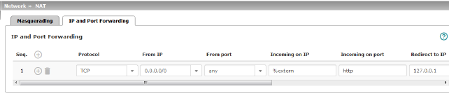
Lists the rules defined for port forwarding (DNAT = Destination NAT). IP and port forwarding performs the following: the headers of incoming data packets from the external network, which are addressed to the external IP address (or one of the external IP addresses) of the mGuard and to a specific port of the mGuard, are rewritten in order to forward them to a specific computer in the internal network and to a specific port on this computer. In other words, the IP address and port number in the header of incoming data packets are changed. IP and port forwarding from the internal network behaves as described above. 

|
||
|
Specify the protocol to which the rule should apply. GRE GRE protocol IP packets can be forwarded. However, only one GRE connection is supported at any given time. If more than one device sends GRE packets to the same external IP address, the mGuard may not be able to feed back reply packets correctly. We recommend only forwarding GRE packets from specific transmitters. These could be ones that have had a forwarding rule set up for their source address by entering the transmitter address in the “From IP” field, e.g., 193.194.195.196/32. |
|
|
From IP |
The sender address for forwarding. 0.0.0.0/0 means all addresses. To specify an address area, use CIDR format (see "CIDR (Classless Inter-Domain Routing)" on page 34). Name of IP groups, if defined. When a name is specified for an IP group, the host names, IP addresses, IP areas or networks saved under this name are taken into consideration (see "IP/Port Groups" on page 198). 
|
|
From port |
The sender port for forwarding. any refers to any port. Either the port number or the corresponding service name can be specified here, e.g., pop3 for port 110 or http for port 80. Name of port groups, if defined. When a name is specified for a port group, the ports or port ranges saved under this name are taken into consideration (see "IP/Port Groups" on page 198). |
|
Incoming on IP |
–Specify the external IP address (or one of the external IP addresses) of the mGuard here, or –Specify the internal IP address (or one of the internal IP addresses) of the mGuard here, or –Use the variable %extern (if the external IP address of the mGuard is changed dynamically so that the external IP address cannot be specified). If multiple static IP addresses are used for the WAN port, the %extern variable always refers to the first IP address in the list. |
|
Incoming on port |
The original destination port specified in the incoming data packets. Either the port number or the corresponding service name can be specified here, e.g., pop3 for port 110 or http for port 80. This information is not relevant for the “GRE” protocol. It is ignored by the mGuard. |
|
Redirect to IP |
The internal IP address to which the data packets should be forwarded and into which the original destination addresses are translated. |
|
Redirect to port |
The port to which the data packets should be forwarded and into which the original port data is translated. Either the port number or the corresponding service name can be specified here, e.g., pop3 for port 110 or http for port 80. This information is not relevant for the “GRE” protocol. It is ignored by the mGuard. |
|
Comment |
Freely selectable comment for this rule. |
|
Log |
For each individual port forwarding rule, you can specify whether the use of the rule: –Should be logged – activate Log function –Should not be logged – deactivate Log function (default) |
Network >> DNS >> DNS server |
||
|---|---|---|
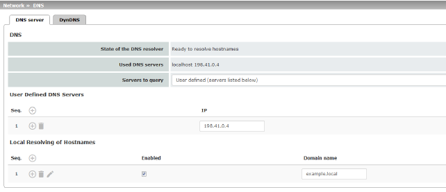
DNS |
If the mGuard is to initiate a connection to a peer on its own (e.g., to a VPN gateway or NTP server) and it is specified in the form of a host name (i.e., www.example.com), the mGuard must determine which IP address belongs to the host name. To do this, it connects to a domain name server (DNS) to query the corresponding IP address there. The IP address determined for the host name is stored in the cache so that it can be found directly (i.e., more quickly) for other host name resolutions. With the Local resolving of hostnames function, the mGuard can also be configured to respond to DNS requests for locally used host names itself by accessing an internal, previously configured directory. The locally connected clients can be configured (manually or via DHCP) so that the local address of the mGuard is used as the address of the DNS server to be used. If the mGuard is operated in Stealth mode, the management IP address of the mGuard (if this is configured) must be used for the clients, or the IP address 1.1.1.1 must be entered as the local address of the mGuard. |
|
|
State of the DNS resolver |
Status of the host name resolution |
|
Used DNS servers |
DNS servers for which the associated IP address was queried. |
|
DNS root servers Requests are sent to the root name servers on the Internet whose IP addresses are stored on the mGuard. These addresses rarely change. Provider defined (i.e., via DHCP) The DNS servers of the Internet service provider (ISP) that provide access to the Internet are used. Only select this setting if the mGuard operates in Router mode with DHCP. The setting can also be used if the mGuard is located in Stealth mode (automatic). In this case, the DNS server that the client uses can be recognized and taken on. User defined (servers listed below) If this setting is selected, the mGuard will connect to the DNS servers listed under User defined DNS servers. |
|
User Defined DNS Servers (Only when User-defined is selected as root server) |
The IP addresses of DNS servers can be entered in this list. If this should be used by the mGuard, select the "User defined (servers listed below)" option under Servers to query. 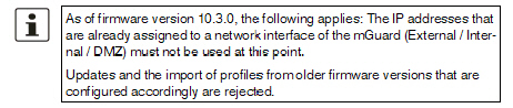
|
|
You can configure multiple entries with assignment pairs of host names and IP addresses for various domain names. You have the option to define, change (edit), and delete assignment pairs of host names and IP addresses. You can also activate or deactivate the resolution of host names for a domain. In addition, you can delete a domain with all its assignment pairs. |
||
|
Creating a table with assignment pairs for a domain: •Open
a new row and click on the Changing or deleting assignment pairs belonging to a domain: •Click
on the After clicking on Edit row, the DNS Records tab page is displayed: 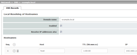
|
|
|
Domain name |
The name can be freely assigned, but it must adhere to the rules for assigning domain names. It is assigned to every host name. |
|
Enabled |
Activates or deactivates the Local Resolving of Hostnames function for the domain specified in the “Domain name” field. |
|
Deactivated: the mGuard only resolves host names, i.e., it supplies the assigned IP address for host names. Activated: as with “Deactivated”. It is also possible to determine the host names assigned to an IP address. |
|
|
Hostnames |
The table can have any number of entries. 
|
|
Host |
Host name |
|
TTL (hh:mm:ss) |
Abbreviation for Time To Live. Default: 3600 seconds (1:00:00) Specifies how long called assignment pairs may be stored in the cache of the calling computer. |
|
IP |
The IP address assigned to the host name in this table row. |
Example: Local Resolving of Hostnames
The “Local Resolving of Hostnames” function is used in the following scenario, for example:
A plant operates a number of identically structured machines, each one as a cell. The local networks of cells A, B, and C are each connected to the plant network via the Internet using the mGuard. Each cell contains multiple control elements, which can be addressed via their IP addresses. Different address areas are used for each cell.
A service technician should be able to use her/his notebook on site to connect to the local network for machine A, B or C and to communicate with the individual controllers. So that the technician does not have to know and enter the IP address for every single controller in machine A, B or C, host names are assigned to the IP addresses of the controllers in accordance with a standardized diagram that the service technician uses. The host names used for machines A, B, and C are identical, i.e., the controller for the packing machine in all three machines has the host name “pack”, for example. However, each machine is assigned an individual domain name, e.g., cell-a.example.com.
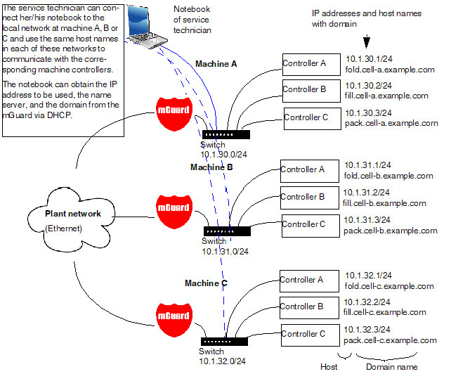
Figure 5-1: Local Resolving of Hostnames
Network >> DNS >> DynDNS |
||
|---|---|---|
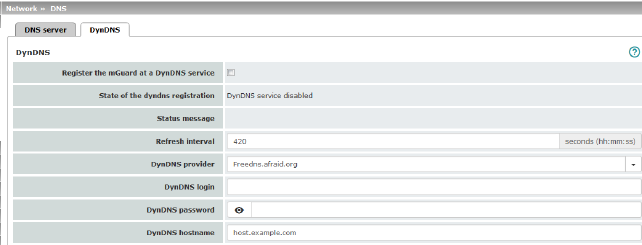
DynDNS |
In order for a VPN connection to be established, at least one partner IP address must be known so that the partners can contact each other. This condition is not met if both participants are assigned IP addresses dynamically by their respective Internet service providers. In this case, a DynDNS service such as DynDNS.org or DNS4BIZ.com can be of assistance. With a DynDNS service, the currently valid IP address is registered under a fixed name. If you have registered with one of the DynDNS services supported by the mGuard, you can enter the corresponding information in this dialog box.
|
|
|
Register the mGuard at a DynDNS service |
Activate the function if you have registered with a DynDNS provider and if the mGuard is to use this service. The mGuard then reports its current IP address to the DynDNS service (i.e., the one assigned for its Internet connection by the Internet service provider). |
|
State of the DynDNS registration |
State of the DynDNS registration |
|
Status message |
Status message |
|
Refresh Interval |
Default: 420 (seconds). The mGuard informs the DynDNS service of its new IP address whenever the IP address of its Internet connection is changed. In addition, the device can also report its IP address at the interval specified here. This setting has no effect for some DynDNS providers, such as DynDNS.org, as too many updates can cause the account to be closed. |
|
The providers in this list support the same protocol as the mGuard. Select the name of the provider with whom you are registered, e.g., DynDNS.org, TinyDynDNS, DNS4BIZ. If your provider is not in the list, select DynDNS-compatible and enter the server and port for this provider. |
|
|
Only visible when DynDNS provider is set to DynDNS-compatible. Name of the server for the DynDNS provider. |
|
|
DynDNS port |
Only visible when DynDNS provider is set to DynDNS-compatible. Number of the port for the DynDNS provider. |
|
DynDNS
|
Enter the user identifier assigned by the DynDNS provider here. |
|
DynDNS password |
Enter the password assigned by the DynDNS provider here. |
|
DynDNS hostname |
The host name selected for this mGuard at the DynDNS service, providing you use a DynDNS service and have entered the corresponding data above. The mGuard can then be accessed via this host name. |
The dynamic host configuration protocol (DHCP) can be used to automatically assign the network configuration set here to the computers connected directly to the mGuard.
You can specify the DHCP settings for the internal interface (LAN port) under Internal DHCP and the DHCP settings for the external interface (WAN port) under External DHCP. DHCP settings for the DMZ interface (DMZ port) can be made under DMZ DHCP.
In the default settings, the DHCP server of the mGuard device is activated by default for the LAN interface (port XF2-4 or XF2-5) (Internal DHCP). This means that network clients connected via the LAN interface automatically receive their network configuration from the mGuard device if they have also activated DHCP. |
The menu items External DHCP and DMZ DHCP are not part of the FL MGUARD 2000 series functionality. |
The DHCP server also operates in Stealth mode. In multi-stealth mode, the external DHCP server of the mGuard cannot be used if a VLAN ID is assigned as the management IP. |
IP configuration for Windows computers: when you start the DHCP server of the mGuard, you can configure the locally connected computers so that they obtain their IP configuration automatically from the mGuard via DHCP. Please also refer to the chapter „Obtaining the IP setting per DHCP (Windows)“, in the user manual UM EN HW FL MGUARD 2000/4000, available at phoenixcontact.net/product/1357828). |
The menu item External DHCP is not part of the FL MGUARD 2000 series functionality. |
Network >> DHCP >> Internal DHCP |
||
|---|---|---|
|
The settings for Internal DHCP and External DHCP are essentially identical and are not described separately in this section. |
|
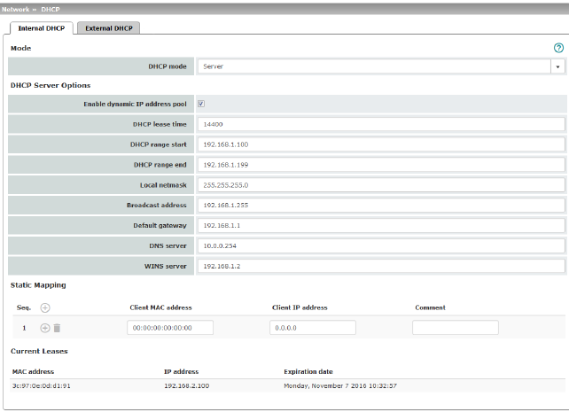
Mode |
Disabled / Server / Relay Set this option to Server if the mGuard is to operate as an independent DHCP server (default setting: Internal DHCP). The corresponding setting options are then displayed below on the tab page (see "DHCP mode: Server" ). Set this option to Relay if the mGuard is to forward DHCP requests to another DHCP server. The corresponding setting options are then displayed below on the tab page (see "DHCP mode: Relay" ). 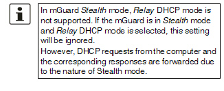
If this option is set to Disabled, the mGuard does not answer any DHCP requests. |
|
|
If DHCP mode is set to Server, the corresponding setting options are displayed below as follows. 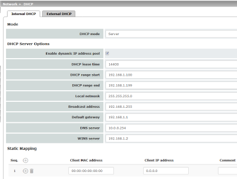
|
|
DHCP Server Options |
Enable dynamic IP address pool: |
When the function is activated, the IP address pool specified under DHCP range start and DHCP range end is used (see below). Deactivate the function if only static assignments should be made using the MAC addresses (see below). |
|
Time in seconds for which the network configuration assigned to the computer is valid. The client should renew its assigned configuration shortly before this time expires. Otherwise it may be assigned to other computers. |
|
|
DHCP range start (With enabled dynamic IP address pool) |
The start of the address area from which the DHCP server of the mGuard should assign IP addresses to locally connected computers. |
|
DHCP range end (With enabled dynamic IP address pool) |
The end of the address area from which the DHCP server of the mGuard should assign IP addresses to locally connected computers. |
|
Local netmask |
Specifies the netmask of the computers. Default: 255.255.255.0 |
|
Broadcast address |
Specifies the broadcast address of the computers. |
|
Specifies which IP address should be used by the computer as the default gateway. Usually this is the internal IP address of the mGuard. |
|
|
DNS server |
Address of the server used by the computer to resolve host names in IP addresses via the Domain Name Service (DNS). If the DNS service of the mGuard is to be used, enter the internal IP address of the mGuard here. |
|
WINS server |
Address of the server used by the computer to resolve host names in addresses via the Windows Internet Naming Service (WINS). |
Static Mapping |
Client MAC address |
To find out the MAC address of your computer, proceed as follows: Windows: •Start ipconfig /all in a command prompt. The MAC address is displayed as the “Physical Address”. Linux: •Call /sbin/ifconfig or ip link show in a shell. |
|
|
The following options are available: –Client/computer MAC address (without spaces or hyphens) –Client IP address |
|
Client IP address |
The static IP address of the computer to be assigned to the MAC address. 


|
Current Leases |
The current leases assigned by the DHCP server are displayed with MAC address, IP address, and expiration date (timeout). |
|
|
If DHCP mode is set to Relay, the corresponding setting options are displayed below as follows. 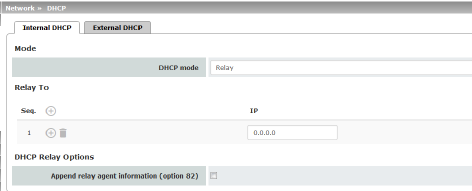
|
|
|
||
|
DHCP servers to relay to |
A list of one or more DHCP servers to which DHCP requests should be forwarded. |
|
Append relay agent information (option 82) |
When forwarding, additional information for the DHCP servers to which information is being forwarded can be appended according to RFC 3046. |
The menu item DMZ DHCP is not part of the FL MGUARD 2000 series functionality. |
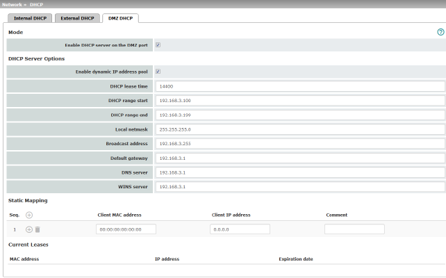
The DHCP server functionality of the mGuard is expanded on its DMZ interface (DMZ port). The mGuard can automatically assign a network configuration to clients connected to the DMZ port via the DHCP protocol.
Network >> DHCP >> DMZ DHCP |
||
|---|---|---|
Mode |
Enable DHCP server on the DMZ port |
Enables the DHCP server on the DMZ interface. If the function is disabled, the mGuard does not answer any DHCP queries on the DMZ interface. |
DHCP Server Options |
Enable dynamic IP address pool: |
When the function is activated, the IP address pool specified under DHCP range start and DHCP range end is used (see below). Deactivate the function if only static assignments should be made using the MAC addresses (see below). |
|
DHCP lease time |
Time in seconds for which the network configuration assigned to the computer is valid. The client should renew its assigned configuration shortly before this time expires. Otherwise it may be assigned to other computers. |
|
DHCP range start (With enabled dynamic IP address pool) |
The start of the address area from which the DHCP server of the mGuard should assign IP addresses to locally connected computers. |
|
DHCP range end (With enabled dynamic IP address pool) |
The end of the address area from which the DHCP server of the mGuard should assign IP addresses to locally connected computers. |
|
Local netmask |
Specifies the netmask of the computers. Default: 255.255.255.0 |
|
Broadcast address |
Specifies the broadcast address of the computers. |
|
Default gateway |
Specifies which IP address should be used by the computer as the default gateway. Usually this is the internal IP address of the mGuard. |
|
DNS server |
Address of the server used by the computer to resolve host names in IP addresses via the Domain Name Service (DNS). If the DNS service of the mGuard is to be used, enter the internal IP address of the mGuard here. |
|
WINS server |
Address of the server used by the computer to resolve host names in addresses via the Windows Internet Naming Service (WINS). |
Static Mapping |
Client MAC address |
To find out the MAC address of your computer, proceed as follows: Windows: •Start ipconfig /all in a command prompt. The MAC address is displayed as the “Physical Address”. Linux: •Call /sbin/ifconfig or ip link show in a shell. |
|
|
The following options are available: –Client/computer MAC address (without spaces or hyphens) –Client IP address |
|
Client IP address |
The static IP address of the computer to be assigned to the MAC address. 


|
Current Leases |
The current leases assigned by the DHCP server are displayed with MAC address, IP address, and expiration date (timeout). |
|
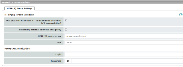
A proxy server can be specified here for the following activities performed by the mGuard itself:
–CRL download
–Firmware update
–Regular configuration profile retrieval from a central location
–Restoring of licenses
Network >> Proxy Settings >> HTTP(S) Proxy Settings |
||
|---|---|---|
The http(s) proxy settings |
Use proxy for HTTP and HTTPS |
When the function is activated, connections that use the HTTP or HTTPS protocol are transmitted via a proxy server whose address and port should also be specified. Connections that are transmitted in encapsulated form using the VPN in TCP encapsulation function are also routed via the proxy server (see "TCP encapsulation" on page 217). 
|
|
HTTP(S) proxy server |
Host name or IP address of the proxy server. |
|
Number of the port to be used, e.g., 3128. |
|
Proxy Authentication |
Login |
User identifier (login) for proxy server login. |
|
Password |
Password for proxy server login. |
In larger company networks, the use of dynamic routing protocols can make it easier for the network administrator to create and manage routes or even eliminate the need for this.
The OSPF (Open Shortest Path First) routing protocol allows participating routers to exchange and adapt the routes for transmitting IP packets in their autonomous network in real time (dynamically). The best route to each subnetwork is determined for all participating routers and entered in routing tables for the devices. Changes in the network topology are automatically sent to neighboring OSPF routers and eventually distributed by them to all participating OSPF routers.
This menu is only available when the mGuard is in “Router” network mode. |
OSPF can be configured for internal, external, and DMZ interfaces. The support of OSPF via IPsec and GRE is currently not available.
Multiple OSPF areas can be configured in order to distribute local routes and learn external routes. The status of all learned routes is displayed in a table.
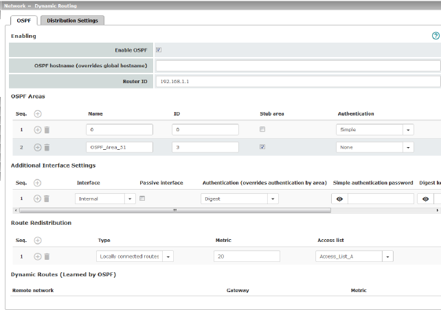
Network >> Dynamic Routing >> OSPF |
||
|---|---|---|
Activation |
Enable OSPF |
When the function is deactivated (default): OSPF is disabled on the device. When the function is activated: dynamic routing using the OSPF protocol is enabled on the device. New routes can be learned and distributed by neighboring OSPF routers. |
|
OSPF hostname |
If an OSPF hostname is assigned here, this is communicated to the participating OSPF routers instead of the global host name. |
|
Router ID |
The Router ID in the form of an IP address must be unique within the autonomous system. It can otherwise be freely selected and typically corresponds to the IP address of the WAN or LAN interface of the mGuard. |
OSPF Areas |
The autonomous system is segmented using OSPF Areas. The routes between OSPF routers are exchanged within an area. The mGuard can belong to one or more OSPF areas. Distribution between neighboring areas is also possible using the “Transition Area” (see below). |
|
|
Name |
The Name can be freely selected (default: ID). An OSPF router is clearly identified by its ID. |
|
ID |
In general, the ID can be freely selected. If an OSPF area is assigned the ID 0, it becomes the “Transition Area”. This area is used to exchange routing information between two neighboring areas and then distribute it. |
|
Stub area |
If the OSPF area is a stub area, activate the function. |
|
Authentication |
None / Simple / Digest Authentication of the mGuard within the OSPF area can be performed using the “Simple” or “Digest” method. The corresponding passwords and digest keys are assigned for the allocated interfaces (see "Additional Interface Settings" ). |
Interface |
Internal / External / DMZ Selects the interface for which the settings apply. If no settings are made here, the default settings apply (i.e., OSPF is enabled for the interface and the passwords are not assigned). |
|
|
Passive interface |
Default: deactivated When the function is deactivated, OSPF routes are learned and distributed by the interface. When the function is activated, no routes are learned or distributed. |
|
Authentication |
None / Digest If Digest is selected, “Digest” is always used for authentication at the selected interface – regardless of the authentication method already assigned to an OSPF area. The authentication method (None / Simple / Digest) that has already been assigned to an OSPF area is therefore ignored and not used. |
|
Simple authentication password |
Password for authentication of the OSPF router (for “Simple” authentication method) |
|
Digest key |
Digest key for authentication of the OSPF router (for “Digest” authentication method) |
|
Digest key ID |
Digest key ID for authentication of the OSPF router (for “Digest” authentication method) (1–255) |
Route Redistribution |
Statically entered routes in the kernel routing table can also be distributed using OSPF. Rules can be created for locally connected networks and networks that are reachable via a gateway. The networks whose routes are to be distributed using OSPF can be specified in “access lists” via the "Distribution Settings" . 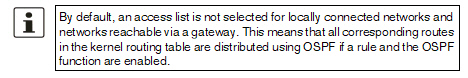
|
|
|
Type |
Locally connected routes / Remotely connected routes Locally connected routes: all local networks are distributed using OSPF, if OSPF is enabled. Distribution can be restricted by using access lists. Remotely connected routes: all external networks are distributed using OSPF. External networks include, for example, static as well as IPsec and OpenVPN remote networks. Distribution can be restricted by using access lists. |
|
Metric |
Metric used to distribute the routes. Unit representing the quality of a connection when a specific route is used (depends on the bandwidth, hop count, costs, and MTU). |
|
Access list |
Distributes the routes according to the selected access list (see "Distribution Settings" ). If None is selected, all routes of the selected type are distributed. |
Dynamic Routes (learned by OSPF) |
The status of all routes learned using OSPF is displayed. |
|
|
Remote network |
Dynamically learned remote network. |
|
Gateway |
Gateway to reach the remote network. |
|
Metric |
Metric for the learned route. |
Dynamic routes are automatically distributed using the OSPF protocol. For statically entered routes in the kernel routing table, it must be specified whether they should also be distributed using OSPF.
If a rule is selected for either the “Locally connected routes” or “Remotely connected routes” type, by default (Access List = None) all corresponding routes are distributed using OSPF if OSPF is enabled. |
Rules can be created via Distribution Settings which determine the routes that are not learned dynamically that should be distributed using OSPF. These include:
–Locally configured networks (see "Network >> Interfaces" on page 109)
–Static routes entered as external, internal or DMZ networks (see "Network >> Interfaces" on page 109)
–Routes entered in the kernel routing table via OpenVPN (see "OpenVPN Client >> Connections" on page 265)
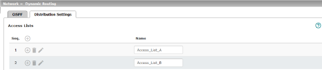
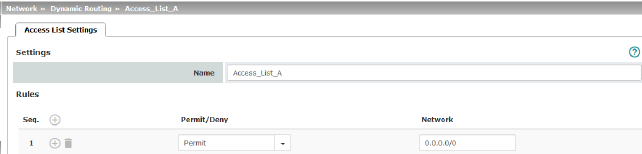
Network >> Dynamic Routing >> Distribution Settings >> Edit >> Access List Settings |
||
|---|---|---|
Name |
The Name must be unique and must not be assigned more than once. |
|
Rules |
Permit/Deny |
Lists the access list rules. These apply for routes that are not distributed dynamically using OSPF. Permit (standard)means that the route to the entered network is distributed using OSPF. Deny means that the route to the entered network is not distributed using OSPF. |
|
Network |
Network whose distribution is permitted or denied by rules. |