
For more information on the General Settings please refer to the following chapters.
6mdm client – Configuration tasks
The Device properties dialog, the Template properties dialog, the Pool Value Properties Dialog, and the VPN group properties dialog are used to configure devices, templates, pools, or VPN groups, respectively. The device and template dialogs are very similar, therefore the common parts are described in this chapter.
Chapter 6.3.3 and Chapter 6.4.3 discuss the differences between the two dialogs. The pool configuration is explained in Chapter 6.5.3. For detailed information on the template and inheritance concept please refer to Chapter 6.4.5 (Working with templates). The VPN group configuration is described in Chapter 6.6.4.
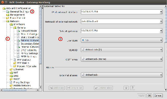
On the left side of the dialog you can find the navigation tree ①, which resembles the menu structure of the mGuard Web GUI. Compared to the mGuard GUI the navigation tree contains an additional entry General Settings ②, which contains template and device parameters only used in mdm.
For more information on the General Settings please refer to the following chapters. |
Navigation tree context menu
The navigation tree has a context menu, which can be opened by clicking on the tree with the right mouse button. The context menu contains various entries to fold/unfold parts of the tree. Furthermore the context menu shows the key shortcuts to access the menu entries.
Navigation tree context menu |
||
|---|---|---|
Focus on Subtree |
Only the subtree of the selected node will be fully expanded. All other currently expanded nodes/subtrees will be collapsed. |
|
Collapse All Other Nodes |
All nodes that are currently not selected will be collapsed. |
|
Scroll to Active Node |
The node that is currently selected will be focused if it is not already visible. |
|
Collapse |
Collapse All Nodes |
All nodes will be collapsed. |
|
Collapse Selected Subtree |
The selected subtree will be collapsed. |
|
Collapse Selected Node |
The selected node will be collapsed. Currently expanded subtrees of the node will appear expanded again, when the node will be expanded the next time. |
Expand |
Expand All Nodes |
All nodes will be fully expanded. |
|
Expand Selected Subtree |
The selected subtree will be fully expanded. |
|
Expand Selected Node |
The selected node will be expanded (only one level). |
|
Focus on Here Defined Nodes |
All nodes with values that are not inherited will be expanded (i.e. value types set to custom or local). |
|
Focus on Inherited Nodes |
All nodes with inherited values will be expanded. |
|
Focus on Incomplete Nodes |
All nodes with inherited “None“ values or unsatisfied pool references will be expanded. |
mGuard configuration
The navigation tree allows you to navigate conveniently to the mGuard variables. If you click on a “leaf” of the tree, the corresponding mGuard variables and the associated settings are shown in the right area ③ of the Properties Dialog.
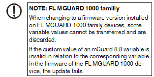
NOTE: Restrictions for FL MGUARD 1000 family devices The new devices of the FL MGUARD 1000 family (FL MGUARD 1102/1105) configurable in mdm 1.12.x support fewer functions and variables than the devices of the FL/TC MGUARD 2000/4000 family (MGUARD2 platform). Therefore, some of the functions described below are not available on these devices. After updating the firmware version to mGuard NT 1.3, check whether all settings have been applied according to your requirements. Inherited table entries (firewall rules) should be checked carefully if one of the parent tables (Incoming or Outgoing) is set to "Local" / "None". |
Depending on the variable, different value types can be selected (exemplarily shown for the Device properties dialog, see below).
Different value types of variables |
||
|---|---|---|
Variables with a fixed value set |
|
|
Inherited |
Set the variable to the default value or to the value defined in an assigned template (if applicable). The usage of templates and inherited values is further explained in “Template properties dialog” on page 99 and “Working with templates” on page 106. |
|
Local |
The mGuard supports (among others) two roles, the admin who is able to change all mGuard variables and the netadmin who is able to change only local variables. The Local value determines whether a variable is local, i.e. whether or not it can be managed by the netadmin on the mGuard. If a variable is local, it will not be managed by mdm anymore in order to avoid conflicts between mdm and the netadmin. Note: The Local value is not supported for FL MGUARD 1000 devices/templates with installed firmware mGuardNT 1.3. On an FL MGUARD 1000 device or in mGuardNT 1.3 templates an inherited value "Local" is replaced by "None". |
|
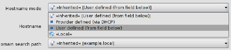
Fixed values |
A number of fixed values which can be selected for this variable. The selectable values depend on the variable. In the example above (see figure) the fixed values are: Provider defined and User defined for the variable Hostname mode. |
|
Different value types of variables |
||
|---|---|---|
Variables with an editable value |
|
|
|
Inherited |
See above. |
|
Local |
See above. |
|
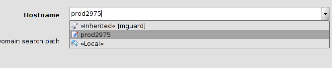
Custom |
If you select the Custom value entry, the combo box becomes editable and you can enter a specific value for the variable, e.g. prod2975 in the example in the figure above. The value you entered is subsequentely shown as available selection in the combo box. |
Different value types of variables |
||
|---|---|---|
Table variables (e.g. incoming firewall rules) |
Table variables allow the following choices (for more information on tables please see “Modifying mGuard table variables” on page 67). 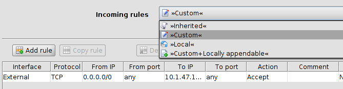
|
|
|
Inherited |
Set the variable to the default rows or to the rows defined in an assigned template (if applicable). The inherited rows are shown at the beginning of the table in a different color and are not editable or selectable. The usage of templates and inherited values is further explained in “Template properties dialog” on page 99 and “Working with templates” on page 106. |
|
Local |
See above. |
|
Custom |
If you select Custom the table and its associated menu elements become enabled. Table rows defined in a template may be copied from the template to the device. They can be deleted and edited or new rows can be added in the Device properties dialog (only in certain cases: see described behavior below). 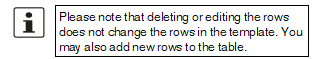
Behavior (only permission setting May override ): General case: In general, switching the table from Inherited to Custom overrides the table completely, i.e. the table content defined at the template is not retained on the device, but default table rows are set (e.g. Firewall Outgoing Rules). Exception: If the table has no default row (i.e. the table is empty), as a convenience, after switching from Inherited to Custom the table content inherited from the template is copied into the Custom table on the device in the form of new rows (e.g. Firewall Incoming Rules). Workaround for the general case: For the general case, there is a possibility of enforcing the copy of the inherited table rows: set the table as Custom, remove the default row(s), set the table back to Inherited, and then back again to Custom. The resulting Custom table will have copied the rows from its parent template. 
|
|
Custom + Locally appendable (Device properties dialog only) |
Basically the same as Custom, but this option allows the user netadmin on the mGuard to add further rows. (The rows defined in mdm cannot be edited or deleted by the user netadmin on the mGuard.) |
Different value types of variables |
||
|---|---|---|
Complex table variables (e.g. VPN connections) |
Contrary to “normal” table variables, adding a row to or deleting a row from a complex table variable additionally adds or deletes a node from the navigation tree. An example for a complex table variable are the VPN connections: a VPN connection is represented by a table row in the overview table and by an additional node in the navigation tree, in which the settings for the connection can be made. Please note that the table cells of complex tables are not editable, i.e. all settings have to be made in the leafs of the navigation tree node. Complex table variables allow the following choices (for more information on tables please see “Modifying mGuard table variables” on page 67. 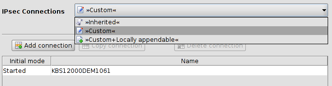
|
|
|
Inherited |
The behavior is basically the same as described for the “normal” table variables above. Inherited rows from a template which also appear as navigation tree nodes are all set to read-only if Inherited is selected for the complex table variable. The usage of templates and inherited values is further explained in “Template properties dialog” on page 99 and “Working with templates” on page 106. |
|
Custom |
If you select Custom the table and its associated menu elements become enabled. Contrary to “normal” table variables the inherited table rows are not copied from the template to the device when switching to Custom. Inherited rows cannot be deleted, but can be edited if Custom is selected. Please note that changing or editing the rows does not change the rows in the template. You may also add new rows (nodes) to the table. 
|
Additional configuration in the template
In the Template properties dialog you can find additional settings for the variables. These settings are explained in “Template properties dialog” on page 99.
6.1.3Indication of invalid input
Invalid input will be immediately indicated by a red variable name and by error icons in the navigation tree, as shown in the following figure for the external IP address:
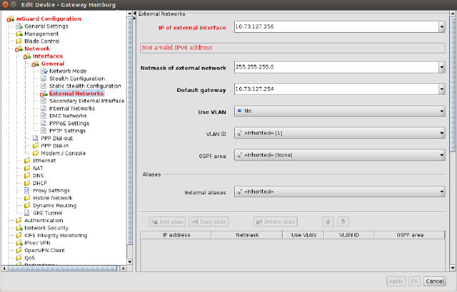
Figure 6-1 Input verification / invalid input
6.1.4Indication of changed values
The
 icon in the leafs of
the navigation tree (see the following figure) indicates that a change
has been made to a variable in the leaf but has not been applied yet.
icon in the leafs of
the navigation tree (see the following figure) indicates that a change
has been made to a variable in the leaf but has not been applied yet.
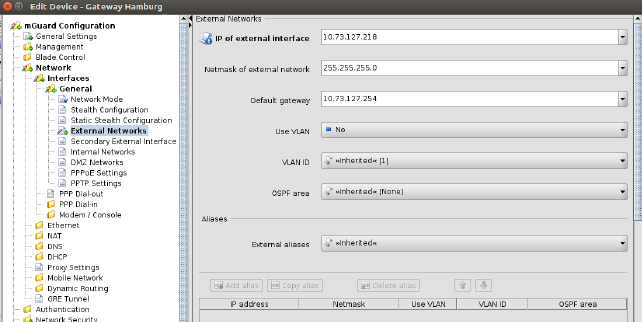
Figure 6-2 Indication of non-applied changes
The
 icon in the leafs of the navigation
tree (see the following figure) indicates that settings have been changed
in the respective leaf and have been applied.
icon in the leafs of the navigation
tree (see the following figure) indicates that settings have been changed
in the respective leaf and have been applied.
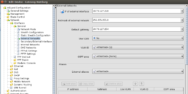
Figure 6-3 Indication of applied changes
6.1.5Indication of “None“ value or exhausted pool
NOTE: Restrictions for FL MGUARD 1000 family devices The new devices of the FL MGUARD 1000 family (FL MGUARD 1102/1105) configurable in mdm 1.12.x support fewer functions and variables than the devices of the FL/TC MGUARD 2000/4000 family (MGUARD2 platform). Therefore, some of the functions described below are not available on these devices. After updating the firmware version to mGuard NT 1.3, check whether all settings have been applied according to your requirements. |
The icon in
the leafs of the navigation tree (see the following figure) indicates
either
icon in
the leafs of the navigation tree (see the following figure) indicates
either
–a “None“ value which has not been overridden (set) yet in the template hierarchy or
–a reference to an exhausted pool.
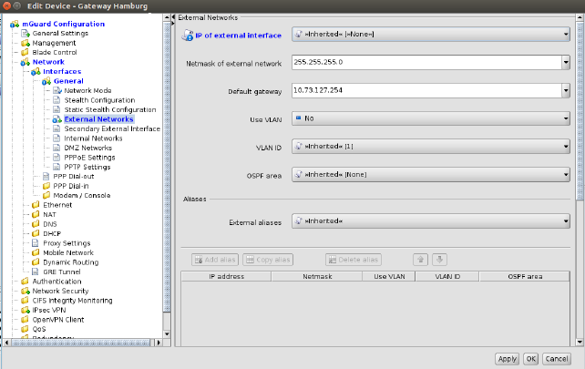
Figure 6-4 Indication of a “None“ value or an exhausted pool
6.1.6Modifying mGuard table variables
The following figure shows an example of a table variable (incoming firewall rules):
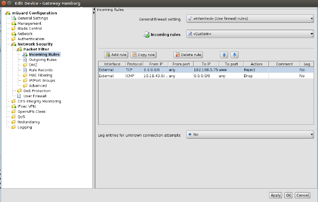
Figure 6-5 Modifying table variables
Add, delete, copy, or move rows
To add, delete, copy, or move rows, please use the respective buttons.
If none of the rows is selected then a click on the Add button will add the row at the beginning of the table. If one or more rows are selected, a new row will be added after the last selected row.
The Delete button is enabled only if at least one row is selected. It deletes the selected rows.
The Copy button is enabled only if at least one row is selected. It copies the selected rows and inserts them after the last selected row.
The
Move buttons are enabled only if at least
one row is selected. To move the current selection up one row press the
![]() button; to move it down please press the
button; to move it down please press the ![]() button.
button.
The Add, Delete, Copy, and Move buttons are enabled only if either Custom or Custom + locally appendable is selected. Please refer to the Section mGuard configuration above. |
Selecting table rows
By clicking on a table row with the left mouse button you select it. Multiple rows can be selected as a contiguous block of rows either by first selecting the upper or lower row of the block and then selecting the opposite row with a left click while holding the <Shift> key.
Rows can be added to the selection or removed from the selection by clicking with the left mouse button on the row while pressing the <Ctrl> key.
Changing a table cell
To edit a table cell please double click on the cell with the left mouse button. (A single click selects the table row).
Invalid values in tables
An invalid value in a table will not be indicated in the navigation tree, but the cell will be marked red. If you enter an invalid value in a table cell, and leave the cell e.g. by clicking on another navigation tree node, the last applied (valid) value will replace the invalid input.
In Firewall tables: If the chosen protocol is neither TCP nor UDP, the configured port will be ignored. In this case the cell will be marked in yellow.
Row colors
The rows of a table may have different colors, depending on the type of row. Inherited rows from an ancestor template are colored red, green or grey:
–a green row indicates that the row is editable,
–a red row indicates that the row cannot be edited or deleted,
–a grey row indicates that it is an inherited default row (which can be changed)
To change a green or grey row it is necessary to switch the value of the table from Inherited to Custom. |
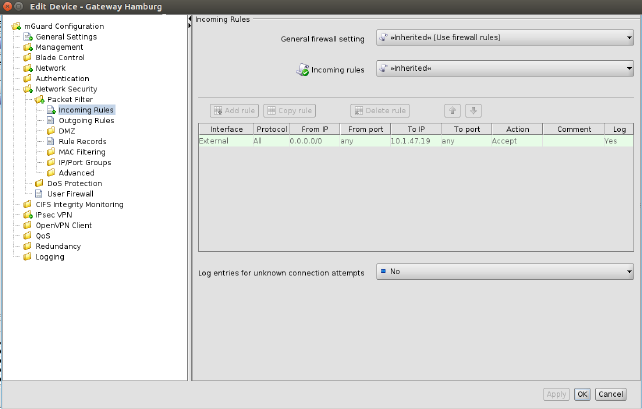
Figure 6-6 Table row colors
Context menu
Tables can also be edited using the context menu. Please click on the table with the right mouse button. The following menu will appear:
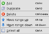
Figure 6-7 Context menu
6.1.7Modifying complex table variables
For the definition of a complex table variable please refer to the section mGuard configuration above. Basically the previous section also applies to complex table variables. However there are some differences that the user should be aware of.
The following figure shows an example of a complex table variable (VPN connections):
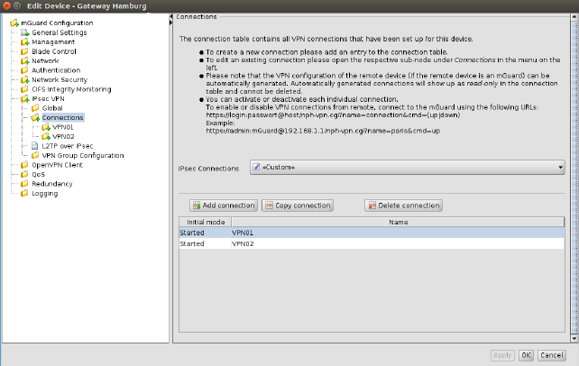
Figure 6-8 Modifying complex table variables
A complex table does not allow to move rows (the respective buttons are missing). Furthermore the cells of complex tables cannot be edited. Adding a row to a complex table also results in adding a node to the navigation tree (see Figure 6-8).
The Add, Copy, and Delete buttons are enabled only if Custom or Custom+Locally appendable is selected. Please refer to the Section mGuard configuration above. |
6.1.8Applying changes to the configuration
Changes made to the configuration are permanently stored with the Apply button (at the bottom of the dialog). If you make any changes without applying them, you can discard your changes by closing the dialog with the Cancel button. You can also apply your changes by closing the dialog with the OK button.
Please note that the configuration is not automatically transferred to the mGuard after applying a change. To transfer the configuration to an mGuard, you have to upload the configuration file to the mGuard (see Chapter 7.1). |
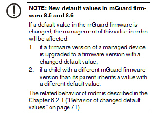
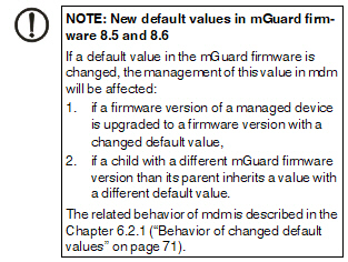
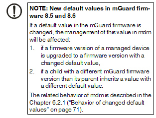
If a default value is changed in the mGuard firmware, the management of this value in mdm will be affected:
1.if a firmware version of a managed device is upgraded to a firmware version with a changed default value,
2.if an inheriting child with a different mGuard firmware version than its parent inherits a value with a different default value.
The related behavior of mdm is described below.
6.2.1Behavior of changed default values
In mGuard firmware version 8.5 and 8.6 the following default values have been changed (see Table 6-1 on page 71:).
Changed in version |
Path to value in the mGuard web interface |
Value old |
Value new |
|
8.5.0 |
IPsec VPN >> Connections >> EDIT >> IKE Options >> ISAKMP SA (Key Exchange) |
3DES (Encryption) |
AES-256 |
|
8.5.0 |
IPsec VPN >> Connections >> EDIT >> IKE Options >> IPsec SA (Data Exchange) |
3DES (Encryption) |
AES-256 |
|
8.6.0 |
CIFS Integrity Monitoring >> CIFS Integrity Checking >> Settings >> Checking of Shares |
SHA-1 (Hash) |
SHA-256 |
|
8.6.0 |
OpenVPN Client -> Connections >> EDIT >> Tunnel Settings >> Data Encryption |
Blowfish (Encryption) |
AES-256 |
|
8.6.0 |
Redundancy >> Firewall Redundancy >> Redundancy >> Encrypted State Synchronization |
3DES (Encryption) |
AES-256 |
|
8.6.0 |
SHA-1 (Hash) |
SHA-256 |
||
8.5.0 |
Network Security >> Packet Filter >> Incoming/Outgoing |
See mGuard firmware manual 8.5.x for further information, avaliableonline or at phoenixcontact.net/products. |
||
If a device/template is upgraded to an mGuard firmware version (8.5 or 8.6), and a new default value differs from the old default value (see table above), the following applies:
If the default value is in default configuration and inherited (along the complete inheritance chain), then the old default value will be kept after the upgrade. In this case the value type (of the table) will be changed from “Inherited“ to “Custom“.
6.2.2Inheritance of changed default values
The inheritance of changed default values depends on the installed mdm version and the mGuard firmware version of the affected device/template.
General behavior in mdm < 1.8.0:
If default values (value type = “Inherited“ and not “Local“ or “Custom“) of the child differ from the default values of the parent (value type = “Inherited“ along the complete inheritance chain), the inheritance will behave as follows:
1.The child keeps the default values corresponding to the child‘s firmware version. The value type will remain „Inherited“.
General behavior in mdm 1.8.0 or later:
If default values (value type = “Inherited“ and not “Local“ or “Custom“) of the child differ from the default values of the parent (value type = “Inherited“ along the complete inheritance chain), the inheritance will behave as follows:
1.Default values that have been changed in mGuard firmware versions < 8.5:
–The child keeps the default values corresponding to the child‘s firmware version. The value type will remain „Inherited“.
2.Default values that have been changed in mGuard firmware versions 8.5 or later:
–The child inherits the default values of the parent. The value type will remain „Inherited“.
General behavior when inheriting values to FL MGUARD 1000 devices or mGuardNT 1.3 templates:
If an FL MGUARD 1000 device or mGuardNT 1.3 template inherits values from devices/templates with installed firmware version 5.0 - 8.8.x, the following applies:
–The inheriting FL MGUARD 1000 device/template always keeps its own default values. The value type remains "Inherited".
–The “Local“ value is not supported for FL MGUARD 1000 devices/templates with installed firmware mGuardNT 1.3:
–On an FL MGUARD 1000 device or in mGuardNT 1.3 templates an inherited value "Local" is replaced by "None".
–The inheritance of values from tables, especially firewall tables, changes the corresponding permissions and values.
–NOTE: Check all values and permissions in tables after they have been inherited to an FL MGUARD 1000 device/mGuardNT 1.3 template.
–Inherited table entries (firewall rules) should be checked carefully if one of the parent tables (Incoming or Outgoing) is set to "Local" / "None".
NOTE: Restrictions for FL MGUARD 1000 family devices The new devices of the FL MGUARD 1000 family (FL MGUARD 1102/1105) configurable in mdm 1.12.x support fewer functions and variables than the devices of the FL/TC MGUARD 2000/4000 family (MGUARD2 platform). Therefore, some of the functions described below are not available on these devices. After updating the firmware version to mGuard NT 1.3, check whether all settings have been applied according to your requirements. |
Please select the Device tab to access the device overview table.:
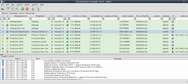
Figure 6-9 mdm main window with device table
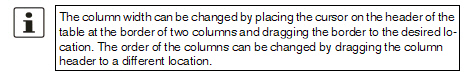
Device table columns
The device overview table contains the following columns (see below).
The column width can be changed by placing the cursor on the header of the table at the border of two columns and dragging the border to the desired location. The order of the columns can be changed by dragging the column header to a different location. |
Device table columns |
||
|---|---|---|
Status C |
The column labeled with C shows the configuration status of the device, which indicates whether the configuration on the mGuard differs from the configuration of the device in mdm. The configuration status can take the following values. |
|
|
Unknown |
mdm is not able to determine whether the configuration of your mGuard is up-to-date. |
|
OK |
The configuration in mdm is identical to the current configuration of your mGuard. |
|
Changed |
The configuration in mdm is different to the current configuration of your mGuard, i.e. the changes made with mdm have not yet been uploaded to the device. |
|
Locked |
The configuration is locked by another user. This can happen if another user opens the Device properties dialog or the Template properties dialog of an assigned template. 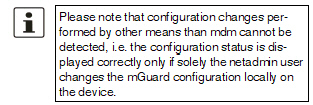
|
Status U |
The column labled with U shows the upload status of the device, which indicates the status of a pending upload or the result of the last upload. Please refer to “Upload configurations to mGuard devices” on page 131 on how to upload configurations to the devices. The upload status can take the following values. |
|
|
Unknown |
mdm could not determine the status yet, since no upload has taken place. |
|
Up to date |
The configuration on the device has not changed because it already was up to date. |
|
Updated |
The configuration on the device has been updated. |
|
Configuration exported |
The configuration files have been successfully exported to the file system. |
|
Pull feedback received |
The mdm server has received a configuration pull feedback from the HTTPS server, but it could not be determined whether the configuration on the device is now up to date. This status indicates that the device has pulled a configuration file, but has not yet applied it, or that the configuration is outdated, because it has been changed in mdm after the export to the HTTPS server. |
|
Device credentials update |
Indicates that an SSH host key reset was performed. |
|
Configuration
|
mdm indicates that the current configuration is invalid, e.g. a None value (see “Template configuration” on page 105) in the template has not been overriden in the device. |
|
Upload or export error |
A permanent error has occured and mdm could not recover from the error or the maximum number of retries for the SSH configuration push has been reached without accessing the mGuard. The cause of the error is displayed in the log window. – Host authentication failed – User authentication failed – I/O failed / Upload failed – Concurrent configuration upload – Configuration rejected |
|
Upload timeout |
This indicates that the SSH connection to the device has timed out, i.e. the device has no reacted to the commands initiated by the mdm within a given (configurable) time frame. If the configuration contains a large number of VPN connections, it might be necessary to increase the timeout; see Chapter 10.1, node service » storage » update » ssh » deadPeerDetectionTimeout (“Key deadPeerDetectionTimeout” on page 187). |
|
License could not be installed |
This indicates that an mGuard license file could not be installed on the device. |
|
Pull configuration rolled back |
This indicates that a configuration pulled by the device was rolled back. |
|
Pull configuration blocked due to previous rollback |
This indicates that configuration is blocked due to a previous rollback. |
|
Saving configuration for rollback failed |
This indicates that saving the rollback configuration failed, the configuration was not applied. |
|
Pulled configuration invalid |
This indicates the device detected an invalid pull configuration and therefore the configuration was not applied. |
|
Firmware upgrade failed |
The scheduled firmware upgrade failed. |
|
Queued for upload or export |
The device is currently in the upload queue. Depending on the settings for the configuration push retries and the waiting time between retries the device might stay in the queue for a while. |
|
Upload or export running |
The device has been accessed and the configuration file is currently being uploaded. |
|
Requeued for upload or export |
If the device is not accessible, then it will be requeued and after waiting time between retries the upload will start again. If after configuration push retries the device has not been accessed an error is shown. This icon is also shown during an ongoing firmware upgrade, since mdm will periodically poll the device for the result of the firmware upgrade. |
Management ID |
The column shows the Management ID of the device. |
|
Templates |
The column shows a comma-separated list of the device’s ancestor templates. The first item in the list is the immediate parent template. |
|
Status V |
The column labled with V shows the VPN group status. |
|
|
Not a member of a VPN group |
Hovering over one of the latter two icons with the mouse cursor will display a tooltip, listing the VPN group(s) in which the device is a member. |
|
Member of exactly one VPN group |
|
|
Member of more than one VPN group |
|
Version |
The column shows the firmware version currently selected in mdm for this device. |
|
Status F |
The column labled with F shows the Firmware status. |
|
|
Unknown |
The status is unknown. |
|
OK |
The firmware upgrade was successful and the firmware version configured in mdm corresponds to the firmware version on the device. |
|
Upgrade scheduled |
The upgrade is scheduled. |
|
Upgrade running |
The upgrade is running. |
|
Version mismatch |
The Firmware version configured in mdm and firmware version on device do not match. |
|
Error |
An error occured during firmware upgrade. |
Version on device |
The column shows the firmware version currently installed on the device. Please refer to “Device properties dialog” on page 88 for more information. If the device is in redundancy mode (see “Redundancy mode” on page 151 for more details), the firmware versions of both devices, separated by a comma, are shown. |
|
The column shows the IP address or hostname which is used by mdm to access the device. This address can be configured in the General settings of the Device properties dialog (see “Device properties dialog” on page 88). Without an Accessible via address it is not possible to push configurations to the device, import ATV profile configurations or open the Web GUI of the device. Please note that this address might not correspond to the internal or external address of the mGuard if NAT is involved. If an SSH port has been set manually in the General settings or is obtained from the configured Port for incoming SHH connections it will be displayed as well. If the device is in redundancy mode (see “Redundancy mode” on page 151 for more details), the Accessible via addresses of both devices, separated by a comma, are shown. |
||
Upload scheduled at |
The column shows the date/time the next configuration upload is scheduled for this device. |
|
Serial number |
The column shows the serial number of this device (see “Device properties dialog” on page 88). If the device is in redundancy mode (see “Redundancy mode” on page 151 for more details), the serial numbers of both devices, separated by a comma, are shown. |
|
Pull config filename |
If the configuration is exported to the file system, a unique ID is used as name of the configuration file. The filename of the configuration file is shown in this column. |
|
Location |
The column shows the value of the SNMP Location variable (SYS_LOCATION). If the location is empty, a “-” character is displayed. If the device is in redundancy mode (see “Redundancy mode” on page 151 for more details) and different locations are set for each physical device, the locations of both devices, separated by a comma, are shown. |
|
Hardware |
The column shows the hardware flavor of the device. See “Hardware flavors” on page 54 for more details. |
|
Status K |
The column labeled with K shows the size of the ssh and https cryptographic keys on the mGuard. The size will be updated every time the mdm has access to the mGuard (only with devices with installed firmware version 7.5 or later). mGuard devices with installed firmware version < 7.5 will not update this information. |
|
|
Unknown |
The size is unknown. |
|
1024 bits |
The size is 1024 bits. |
|
2048 bits |
The size is 2048 bits. |
|
Key renewal scheduled |
It is recommended to renew 1024 bit keys (see “Set Current Device Credentials” on page 86” for more details). |
Last sync |
The column shows the date on which each device was last synchronized successfully with mdm. Synchronization means either updated by –an SSH upload to the device (upload via SSH), –a pull export to the device via an HTTPS configuration pull server + feedback (prepare pull configuration) or –Upload via REST API (FL MGUARD 1000-Geräte) oder –an online import from the device to mdm (Import ATV Profile). 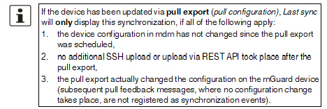
The column can be searched and sorted chronologically. |
|
Filtering and sorting the table
The header of the table can be used to sort the table entries. A click on a header of a column will activate the (primary) sort based on this column. This is indicated by the arrow in the column header. A second click on the same header will reverse the sort order. Clicking on another column header activates the sort based on this new column, the previously activated column will be used as secondary sorting criterion.
The first row of the table accepts the input of regular expressions (please refer to “Glossary” on page 197, Regular expressions), which can be used to efficiently filter the table entries. Filtering based on regular expressions is not used for columns that do not contain text (columns C, U, V, or F).
The filter history will be saved for the current user and can be accessed using the drop down functionality of the filter fields.
Creating devices
There are several ways to create new devices:
1.Open the context menu by clicking on the device table with the right mouse button. To open the Device properties dialog for a new mGuard please select Add in the context menu.
2.Select
the Device tab and click on the  icon
in the menu bar to open the Device properties dialog for
a new mGuard.
icon
in the menu bar to open the Device properties dialog for
a new mGuard.
3.Select New » Device in the main menu to open the Device properties dialog for a new mGuard.
4.Select New » Device Import in the main menu to import new devices.
Editing devices
There are several ways to edit a device:
1.Double-click with the left mouse button on the device in the table to open the Device properties dialog.
2.Select the device with the left mouse button and open the context menu by pressing the right mouse button. Then select Edit to open the Device properties dialog.
3.Select the device to be modified in the device table. Select Edit » Edit Item in the main menu to open the Device properties dialog.
Deleting devices
There are several methods to delete devices:
1.Select the device(s) in the device table and open the context menu by clicking with the right mouse button. To delete the devices please select Delete in the context menu.
2.Select
the devices to be deleted in the table and click on the  icon
in the menu bar.
icon
in the menu bar.
The device context menu contains the following entries (see below).
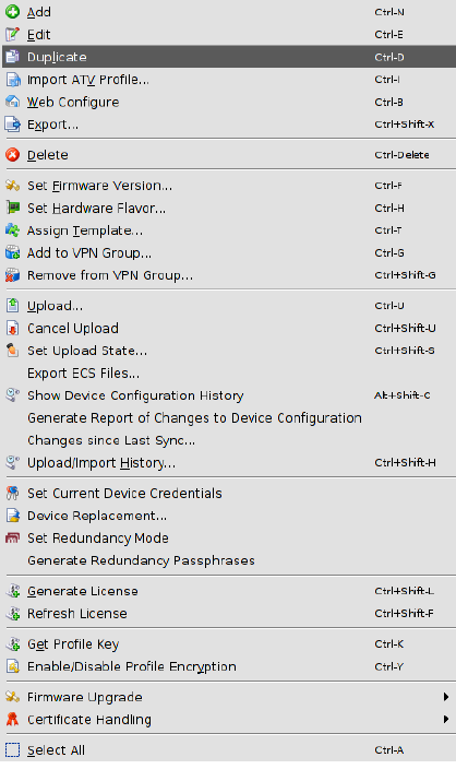
Device context menu |
||
|---|---|---|
|
Add |
Create a new device and open the Device properties dialog of the new device. |
|
Edit |
Edit the selected device (only active if exactly one device is selected in the overview table). |
|
Duplicate |
To create a duplicate of a device please open the context menu by clicking with the right mouse button on the device in the device table. Select Duplicate in the context menu. mdm will create a copy of the device and append the string _copy<n> (<n> is a number) to the Management ID of the new device. Please note that the Duplicate menu entry is only enabled if exactly one device is selected in the device table. |
|
Import ATV Profile |
Import ATV profiles into the selected device(s): 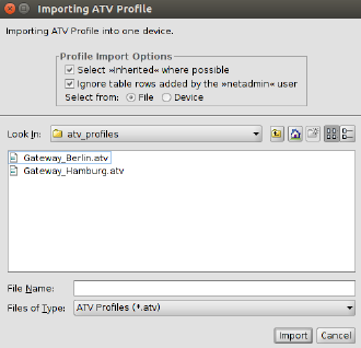
Figure 6-10 ATV import The following options are available when importing a profile: Select Inherited where possible If this option is selected, variables, for which the imported value (i.e. the value in the ATV profile) is the same as the inherited value, are set to Inherited. Otherwise, all variables contained in the profile are set to Custom, regardless of their value. |
|
|
Ignore table rows added by the netadmin user Tables rows that were created by the local netadmin user on the mGuard are not imported. Select from File/Device If File is selected, the ATV profile to import is uploaded as a file. This option is only available if an ATV import into a single device is performed. If Device is selected, mdm downloads the ATV profile from the mGuard. This requires that mdm can log into the mGuard with the ssh protocol or via the REST API (in case of FL MGUARD 1000 devices); the Accessible via address must be set. The related SSH port can be configured optionally (see “Accessible via” on page 91). |
|
|
Import into <A>/<B> If the device is in redundancy mode (see “Redundancy mode” on page 151 for more details), the profile can be imported into the configuration variables for the first or the second physical device. A few configuration variables cannot be imported and must be set manually if necessary: the passwords of the root and admin users, the passwords of the user firewall users, and certificate revocation lists (CRLs). ATV profiles downloaded from an mGuard either do not contain these variables at all or contain them in encrypted (hashed) form. Please note that mdm does import the password of the netadmin user if it is found in the ATV profile, but a profile downloaded from an mGuard does not contain it. |
|
Web Configure |
Open the Web GUI of the device, if the device is accessible (see also Accessible via address in “Device properties dialog” on page 88) 
. |
|
Export |
Generate a CSV file containing the basic properties (but not the configurations) of the selected devices. The file is suitable to imported into mdm again (see “mdm main menu” on page 47, Device Import. |
|
Delete |
Delete the selected devices. |
|
Set Firmware Version |
Upgrade the firmware version to a new version. Since different firmware versions of the mGuard software have different sets of variables, the firmware version corresponding to the installed firmware on the mGuard has to be selected here. 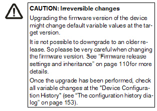

Please refer to “Manage firmware upgrades with mdm” on page 147 for more details. |
|
Set Hardware Flavor |
Set the hardware flavor. Please refer to “Hardware flavors” on page 54 for more details. |
|
Assign Template |
Open the Assign template dialog and assign a template to the selected devices. |
|
Add to VPN Group |
Opens a dialog to add the selected devices to a VPN group. |
|
Remove from VPN Group |
Opens a dialog to remove the selected devices from a VPN group. |
|
Upload |
Open the Upload dialog. Please refer to “Upload configurations to mGuard devices” on page 131 for more details. |
|
Cancel Upload |
Cancel the scheduled upload for the selected devices. |
|
Set Upload State |
The upload status will never be set to successfully uploaded automatically if no push upload is performed and no pull feedback from the configuration server is received (e.g. in a usage scenario where the exported configuration profiles are installed manually on the devices). You can use this option to set the upload state to successfully uploaded manually. Please select the device in the device table, open the context menu with a right click and then select Set upload state. 
|
|
Export ECS Files |
Download (encrypted) ECS files for the selected devices. Per default the ECS files will be encrypted. The user root and other authorized users can disable encryption and download unencrypted ECS files. (For granting rights to authorized users see “Manage users, roles, and permissions” on page 139). ECS files can be used to configure mGuard devices that support this mechanism through SD cards; please refer to the mGuard firmware manual for more details. A dialog is opened where the directory where to store the ECS files can be selected. 
|
|
Show Device Configuration History |
Open the configuration history dialog. Please refer to “The configuration history dialog” on page 153 for more detailed information. |
|
Generate Report of Changes to Device Configuration |
Open a dialog to generate a report of changes to device configurations. Please refer to “Report of changes” on page 160 for more detailed information. |
|
Changes since last Sync |
A configuration dialog opens, showing performed changes since last synchronization. Synchronization means either –an SSH upload to the device (upload via SSH), –a pull export to the device via an HTTPS configuration pull server + feedback (prepare pull configuration), –upload via REST API (FL MGUARD 1000 devices) or –an online import from the device to mdm (Import ATV Profile). If the device has been successfully synchronized once, the configuration changes since the last upload/online import are shown. 
The behavior is similar to selecting two history entries in the "Device Configuration History" Dialog and clicking on "Compare..." (see “Comparison of historic configurations” on page 157). If the device has never been synchronized, the configuration changes since the device was created are shown. If the current configuration is the last synchronized configuration, the current configuration is shown. |
|
Upload/Import History |
Displays an overview of the last synchronization actions. Synchronization means either –an SSH upload to the device (upload via SSH), –a pull export to the device via an HTTPS configuration pull server + feedback (prepare pull configuration), –upload via REST API (FL MGUARD 1000 devices) or –an online import from the device to mdm (Import ATV Profile). |
|
Open a dialog in which the device credentials can be set. The following attributes can be set: Active root and admin passwords The active passwords are the passwords that are currently in effect on the device. They may differ from the configured passwords when the current configuration has not yet been uploaded to or been pulled from the mGuard. mdm keeps track of the active passwords since the root password is needed to set a new root password, and the admin password is needed to log into the mGuard. Reset SSH Host Key mdm stores the SSH key of an mGuard after the initial contact. In case an mGuard has been replaced, the SSH keys do not match and mdm will refuse any connection to the replaced device. This function can be used to reset the SSH key. Renew Secure Key Length |
|
|
|
If this is selected, the mGuard will generate ssh and https keys on the next configuration upload or pull. 
|
|
Device Replacement |
Resets all settings specific to a device to default values. This can be used if a defective device has been replaced. –The following settings are reset: –Firmware Version on Device –Serial Number –Flash ID –SSH Hostkey –Profile Encryption Key –Licenses associated with the device |
|
Set Redundancy Mode |
Open a dialog in which redundancy mode can be enabled or disabled for the selected devices. |
|
Generate Redundancy Passphrases |
Set the redundancy passphrase variables in the device configuration to random values. |
|
Generate License |
Please refer to “Manage license vouchers and device licenses” on page 136 for details regarding the license management. |
|
Refresh License |
Please refer to “Manage license vouchers and device licenses” on page 136 for details regarding the license management. |
|
Get Profile Key |
Obtain a profile key from the license server. Please refer to section ““Profile encryption” on page 133” or details. |
|
Enable/Disable profile encryption |
Enable or disable encryption of configuration profiles for the selected devices. Please refer to section ““Profile encryption” on page 133” for details. |
|
Firmware Upgrade » Schedule upgrade to latest patches |
Schedule a firmware upgrade to the latest available patches. Please refer to “Manage firmware upgrades with mdm” on page 147 for more details. |
|
Firmware Upgrade » Schedule upgrade to latest minor release |
Schedule a firmware upgrade to the latest available minor release. Please refer to “Manage firmware upgrades with mdm” on page 147 for more details. |
|
Firmware Upgrade » Schedule upgrade to next major version |
Schedule a firmware upgrade to the next major version. Please refer to “Manage firmware upgrades with mdm” on page 147 for more details. |
|
Firmware Upgrade » Unschedule upgrade |
Unschedule a firmware upgrade. |
|
Certificate Handling » Request additional certificate |
Request a machine certificate for the device and append it to the list of existing machine certificates. Please refer to “Machine certificates” on page 143 for more details. |
|
Certificate Handling » Request replacement certificate |
Request a machine certificate for the device and replace any existing machine certificates with the new one. Please refer to “Machine certificates” on page 143 for more details. 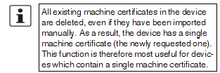
|
|
Certificate Handling » Issue and Export Certificate Requests |
Generate certificate requests for manual certificate enrollment. Please refer to “Machine certificates” on page 143 for more detailed information. |
|
Select All |
Select all devices not excluded by the table filter. |
The Device properties dialog allows to configure the mGuard variables and their associated settings for a device.
For information on how to create, delete or edit devices please refer to “mdm main window” on page 46.
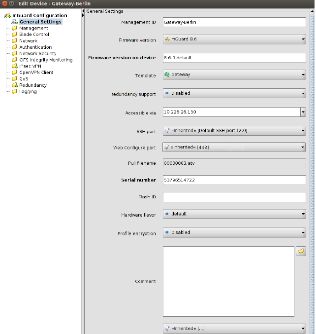
Figure 6-11 Device properties dialog
Similar to the Template properties dialog (see Chapter 6.4.3) the Device properties dialog contains a navigation tree on the left side that resembles the menu structure of the mGuard Web GUI. The navigation tree allows you to conveniently navigate to each mGuard variable.
The Device properties dialog contains the entry General settings for the configuration of additional parameters related to mdm. The following parameters can be set in the General settings.
Device properties dialog |
||
|---|---|---|
General Settings |
Management ID |
This ID is used to identify the device within mdm. The Management ID must be unique. |
|
Firmware version |
Upgrade the firmware version to a new version. Since different firmware versions of the mGuard software have different sets of variables, the firmware version corresponding to the installed firmware on the mGuard has to be selected here. 

|
|
Firmware version on device |
This field represents the firmware version currently installed on the device. It can be manually set, but is overridden with the value found on the device every time a push upload is performed or a pull feedback is received. |
|
Template |
The parent template of the device. |
|
Redundancy support |
The redundancy support of the device can be enabled or disabled. |
|
This is the IP address or hostname used by the mdm server to access the mGuard for an SSH push export of the configuration, a push export to FL MGUARD 1000 devices, an ATV profile import of the configuration or to open the web interface. Please refer to “Upload configurations to mGuard devices” on page 131 for more information on the upload procedure. The following values are available for Accessible via (the SSH port and the Web configuration port can be specified in the fields below. Not online manageable The device is not managed via SSH push. Internal interface in auto stealth mode [1.1.1.1] mdm accesses the mGuard using the address 1.1.1.1 (address of internal interface in automatic stealth mode). Stealth management address mdm accesses the external or internal interface of the mGuard in stealth mode. First external IP address |
|
|
|
mdm accesses the external interface of the mGuard in router mode. First internal IP address mdm accesses the internal interface of the mGuard in router mode. Net zone 1 mdm accesses net zone 1 of the FL MGUARD 1000 device in router mode. Net zone 2 mdm accesses net zone 2 of the FL MGUARD 1000 device in router mode. Custom value A custom value (IP address or hostname) might be required to access the mGuard in NAT scenarios. |
|
SSH port |
This is the SSH port number used by the mdm server to access the mGuard for an SSH push export or an ATV profile import of the configuration. In some cases it might be necessary to change the standard SSH port to connect to the device (e.g. the device is not connected to the Internet but gets a port forwarded from the firewall). If Port for incoming SSH connections is selected, the port configured in Management >> System Settings >> Shell Access >> Shell Access Options >> Port for incoming SSH connections will be used and displayed in the overview table. Please refer to “Upload configurations to mGuard devices” on page 131 for more information on the upload procedure. |
|
Web configuration port |
This is the HTTPS port number used to access the graphical web interface of the mGuard. In some cases it might be necessary to change the standard HTTPS port to connect to the web interface of the device (e.g. the device gets a port forwarded from the firewall). If Remote HTTPS TCP port is selected, the port configured in Management >> Web Settings >> Access >> HTTPS Web Access >> Remote HTTPS TCP port will be used. |
|
Pull filename (read only) |
If the configuration is exported to the file system, a unique ID, which is automatically assigned and cannot be changed, is used as name for the configuration file. The filename is shown in this field. Optionally, additional export files following a different naming scheme can be generated; please refer to “mdm server (preferences.xml file)” on page 183 for more information. |
|
Serial number |
The serial number of the device. The serial number is required for the license handling, especially the license request and refresh (see “Request/generate licenses” on page 136). It can be manually set, but is overridden with the value found on the device every time a push upload is performed or a pull feedback is received. If no push upload is ever performed and no pull feedback is ever received (e.g. in a usage scenario where the exported configuration profiles are installed manually on the devices), the serial number has to be entered here if you would like to create pull configuration filenames containing the serial number. |
|
Flash ID |
The flash ID of the device. The flash ID is required for the license handling, especially for the license refresh (see “Refresh licenses” on page 138). It can be manually set, but is overridden with the value found on the device every time a push upload is performed or a pull feedback is received. |
|
Comment |
An optional comment. |
|
Hardware flavor |
The hardware flavor of the device (see “Hardware flavors” on page 54). Setting it to rs2000 has the effect that variables not supported by this platform are omitted. |
|
Profile encryption |
Enable or disable encryption of configuration profiles for the selected devices. Please refer to section ““Profile encryption” on page 133” for details. |
|
Additional ATV include |
This is a text field for additional settings that should be included in the configuration file of the mGuard. The input has to adhere to the mGuard configuration file conventions. You can also import the contents of a text file in the field by selecting a file with the File Chooser icon. 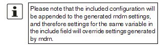
|
NOTE: Restrictions for FL MGUARD 1000 family devices The new devices of the FL MGUARD 1000 family (FL MGUARD 1102/1105) configurable in mdm 1.12.x support fewer functions and variables than the devices of the FL/TC MGUARD 2000/4000 family (MGUARD2 platform). Therefore, some of the functions described below are not available on these devices. After updating the firmware version to mGuard NT 1.3, check whether all settings have been applied according to your requirements. |
Please select the Template tab to access the template overview table.
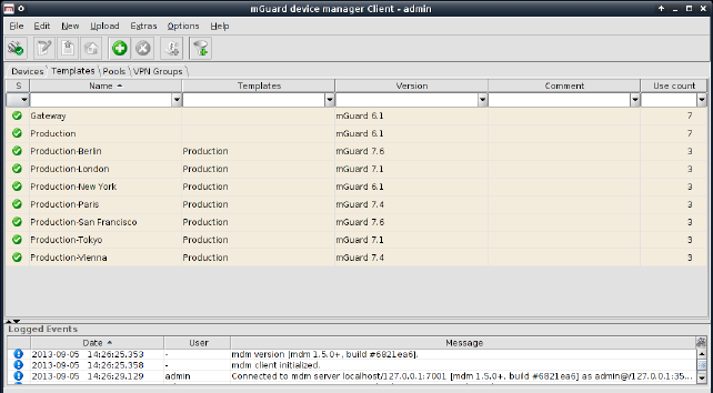
Figure 6-12 The mdm main window with template table
Template table columns
The template overview table contains the following columns.
The column width can be changed by placing the cursor on the header of the table at the border of two columns and dragging the border to the desired location. The order of the columns can be changed by dragging the column header to a different location. |
Template table columns |
||
|---|---|---|
|
Status (S) |
The status icon shows whether the template is currently locked. |
|
Name |
The name assigned to the template. The name can be set in the General Settings of the Template properties dialog (see “Template properties dialog” on page 99). |
|
Templates |
A comma-separated list of the template’s ancestor templates. The first item in the list is the immediate parent template. |
|
Version |
The mGuard firmware version that is used for the template. |
|
Comment |
Optional comment. The comment can be set in the General Settings of the Template properties dialog (see “Template properties dialog” on page 99). |
|
Use count |
This column shows the number of devices or other templates using this template. |
Filtering and sorting the table
The header of the table can be used to sort the table entries. A click on a header of a column will activate the (primary) sort based on this column. This is indicated by the arrow in the column header. A second click on the same header will reverse the sort order. Clicking on another column header activates the sort based on this new column, the previously activated column will be used as secondary sorting criterion.
The first row of the table accepts the input of regular expressions (please refer to Chapter 11, Regular expressions), which can be used to efficiently filter the table entries. Filtering based on regular expressions is not used for the column that does not contain text (i.e. column S).
The
filter criterion for the Use count column
is not interpreted as a regular expression, but as a comma-separated list
of numbers or number ranges
(e.g. 0,2-3).
The filter history will be saved for the current user and can be accessed using the drop down functionality of the filter fields.
Creating templates
There are several ways to create new templates:
1.Open the context menu by clicking on the template table with the right mouse button. To open the Template properties dialog for a new template please select Add in the context menu.
2.Select
the Template tab and click on the  icon
in the menu bar to open the Template properties dialog
for a new template.
icon
in the menu bar to open the Template properties dialog
for a new template.
3.Select New » Template in the main menu to open the Template properties dialog for a new template.
Editing templates
There are several ways to edit a template:
1.Double-click with the left mouse button on the template in the table to open the Template properties dialog.
2.Select the template with the left mouse button and open the context menu by pressing the right mouse button. Then select Edit to open the Template properties dialog.
3.Select the template to be modified in the template table. Select Edit » Edit Item in the main menu to open the Template properties dialog.
Deleting templates
There are several methods to delete templates:
1.Select the template(s) and open the context menu by clicking with the right mouse button. To delete the templates please select Delete in the context menu.
2.Select
the templates to be deleted in the template table and click on the  icon
in the menu bar.
icon
in the menu bar.
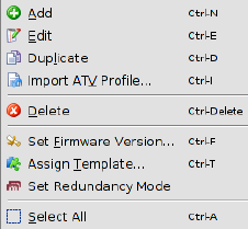
The following entries are available in the context menu of the template overview table.
Template context menu |
||
|---|---|---|
|
Add |
Create a new template and open the Template properties dialog of the new template. |
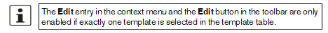
|
Edit |
Edit the selected template (only active if exactly one template is selected in the overview table). |
|
Duplicate |
To create a duplicate of a template please open the context menu by clicking with the right mouse button on the template in the template table. Select Duplicate in the context menu. mdm will create a copy of the template and append the string _copy<n> (<n> is a number) to the name of the new template. Please note that the Duplicate menu entry is only enabled if exactly one template is selected in the template table. |
|
Import ATV Profile |
Import an ATV profile into the selected template(s). This works analogous to the ATV profile import into devices; please refer to “Device context menu” on page 80 for details. |
|
Delete |
Delete the selected templates. |
|
Set Firmware Version |
Upgrade the firmware version to a new version. Since different firmware versions of the mGuard software have different sets of variables, the firmware version corresponding to the installed firmware on the mGuard has to be selected here. 
Please refer to “Manage firmware upgrades with mdm” on page 147 for more details. |
|
Assign Template |
Open the Assign template dialog and assign a parent template to the selected templates. |
|
Set Redundancy Mode |
Open a dialog in which redundancy mode can be enabled or disabled for the selected templates. |
|
Select All |
Select all templates not excluded by the table filter. |
6.4.3Template properties dialog
Templates offer a powerful mechanism to conveniently configure and manage a large number of devices.
By assigning a template to a device (see “Device properties dialog” on page 88), the device inherits the template settings and will use the values that are defined in the template. Depending on the permission settings, the template settings might be overridden in the device configuration.
Please read this chapter for an introduction to the template concept and refer to “Working with templates” on page 106 for detailed information on templates and inheritance.
For information on how to create, delete, or edit templates please refer to “mdm main window” on page 46.
The following screenshot shows the Template properties dialog:
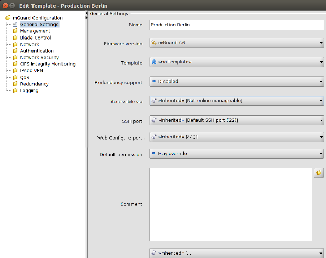
Figure 6-13 Template properties dialog
General settings
Similar to the Device properties dialog (see Chapter 6.3.3) the Template properties dialog contains a menu corresponding to the mGuard’s Web GUI structure on the left side of the window.
Additionally the Template properties dialog contains the entry General settings for the configuration of parameters related to mdm:
Template properties dialog |
||
|---|---|---|
|
Name |
The name of the template. |
|
Firmware version |
Upgrade the firmware version to a new version. Since different firmware versions of the mGuard have different sets of variables, the firmware version (or variable set) the template should use, has to be selected here. 
|
|
Template |
The parent template of this template. |
|
Redundancy support |
The redundancy support of the device can be enabled or disabled. |
|
Accessible via |
This is the IP address or hostname used by the mdm server to access the mGuard for an SSH push export of the configuration, a push export to FL MGUARD 1000 devices, an ATV profile import of the configuration or to open the web interface. Please refer to “Upload configurations to mGuard devices” on page 131 for more information on the upload procedure. The following values are available for Accessible via (the SSH port and the Web configuration port can be specified in the fields below. Not online manageable The device is not managed via SSH push. Internal interface in auto stealth mode [1.1.1.1] mdm accesses the mGuard using the address 1.1.1.1 (address of internal interface in automatic stealth mode). Stealth management address mdm accesses the external or internal interface of the mGuard in stealth mode. First external IP address mdm accesses the external interface of the mGuard in router mode. First internal IP address mdm accesses the internal interface of the mGuard in router mode. Net zone 1 mdm accesses net zone 1 of the FL MGUARD 1000 device in router mode. Net zone 2 mdm accesses net zone 2 of the FL MGUARD 1000 device in router mode. Custom value A custom value (IP address or hostname) might be required to access the mGuard in NAT scenarios. |
|
This is the SSH port number used by the mdm server to access the mGuard for an SSH push export or an ATV profile import of the configuration. In some cases it might be necessary to change the standard SSH port to connect to the device (e.g. the device is not connected to the Internet but gets a port forwarded from the firewall). If Port for incoming SSH connections is selected, the port configured in Management >> System Settings >> Shell Access >> Shell Access Options>> Port for incoming SSH connections will be used and displayed in the overview table. Please refer to “Upload configurations to mGuard devices” on page 131 for more information on the upload procedure. |
|
|
Web configuration port |
This is the HTTPS port number used to access the graphical web interface of the mGuard. In some cases it might be necessary to change the standard HTTPS port to connect to the web interface of the device (e.g. the device gets a port forwarded from the firewall). If Remote HTTPS TCP port is selected, the port configured in Management >> Web Settings >> Access >> HTTPS Web Access >> Remote HTTPS TCP port will be used. |
|
Default Permission |
The permission mdm uses for variables set to Inherited when a device or template inherits from this template. The following permissions can be set: May override Variables set to Inherited have May override permission, i.e. they can be set in the inheriting device or template. |
|
|
May append Table variables set to Inherited have May append permission, i.e. rows can be appended in the inheriting device or template, but existing rows cannot be changed. Other variables set to Inherited have May override permission, i.e. they can be set in the inheriting device or template. No override Variables set to Inherited have No override permission, i.e. they cannot be set in the inheriting device or template. |
|
Comment |
An additional optional comment which is also shown in the template table of the main window. |
|
Additional ATV include |
This is a text field for additional settings that should be included in the configuration file of the mGuard. The input has to adhere to the mGuard configuration file conventions. You can also import the contents of a text file in the field by selecting a file with the File Chooser icon. 
|
As explained above, the navigation tree on the left side of the Template properties dialog resembles the mGuard menu structure.
Figure 6-14 shows an example of the configuration for the external interface.

Figure 6-14 Template configuration
Compared to the Device properties dialog there are additional settings in the template configuration which are explained in the following sections.
For detailed information on the template and inheritance concept please refer to “Working with templates” on page 106.
None value type
In the template None can be selected as value, as you can see in the variable IP of internal interface in Figure 6-14. This means that the template designer does not want to define a value in the template, but wants to make sure the value is overridden in an inheriting template or device. Any attempt to upload a device in which a None value has not been overridden or has been overridden with a Local value results in an error.
Permission setting
In Figure 6-14 the variable Netmask of internal network has an additional permission setting. The permission controls whether and how an inheriting device or template can override the settings. The permission settings can be assigned on a per-variable basis.
Please note that the permission combo box is not visible if Inherited or None is selected as value. |
The following permissions can be selected:
Template Configuration |
||
|---|---|---|
Permissions |
May override |
The value can be changed (overridden) in an inheriting template or device. |
|
No override |
The value cannot be changed in an inheriting template or device. |
|
May append |
This setting is only available for tables (e.g. firewall rules). If a table variable is set to May append, additional table rows can be appended in an inheriting device or template, but the inherited rows cannot be changed or removed. If Local is selected as value and May append as permission, new entries can be added in an inheriting device or template, as well as on the mGuard by the netadmin user. |
Changes made to a template can potentially affect a large number of devices or other templates. Therefore please keep the following rules in mind when working with templates:
–Before making changes to a variable in a template, make sure that the effect on inheriting templates or devices is really desired.
–In particular, changes to a variable permission can have an irreversible effect on inheriting templates or devices. E.g. if a permission is changed from May override to No override, the value of the variable is discarded in all inheriting templates and devices.
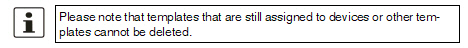
–Templates that are still assigned to devices or other templates cannot be deleted.
This chapter gives more detailed information on the template mechanism.
Inheritance
Templates are the means to efficiently configure a large number of devices. Templates contain the common aspects of a group of devices or a group of child templates. By assigning a template to a child (this may be a device or another template) the child “inherits” the parent template’s settings and may optionally override some of the settings (if the permission in the parent template allows this). Any change made to the parent template will potentially have an impact on all inheriting templates and devices, depending on the setting of the value and permission in the parent template.
The permission setting in a template limits the choices in inheriting templates and devices.
Whether or not a child inherits settings from an ancestor template is indicated by an icon in front of the variable name in the Properties Dialog. If no icon is shown, then either there is no template assigned, or the variable has the value Inherited in all ancestor templates, i.e. no restrictions are defined for this variable.
According to the permissions listed in “Template configuration” on page 105 the following icons are shown in front of the variable name:
 May override.
 No override.
 May append (tables
only).
May append (tables
only).
 No
value defined (value = None), i.e. the value
has to be set in the Device properties dialog or in one of the intermediate templates.
No
value defined (value = None), i.e. the value
has to be set in the Device properties dialog or in one of the intermediate templates.
The following figures illustrate the inheritance mechanism. Figure 6-15 shows the settings for the DHCP server options in the parent template.
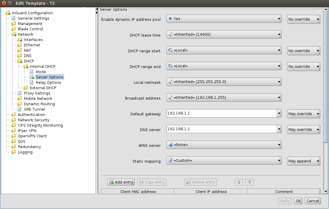
Figure 6-15 Settings in the parent template
Figure 6-16 shows the settings in the device configuration (child). They are the result of values and permissions inherited from the parent template and modifications made in the device.
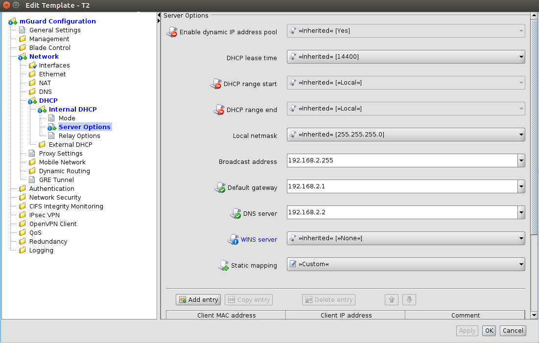
Figure 6-16 Settings in the inheriting device
Settings in the inheriting device |
||
|---|---|---|
|
Enable dynamic IP address pool |
This variable
is set to Yes in the template
and the permission is set to No override.
Therefore the value of the variable cannot be changed in the
device configuration. This is indicated by the disabled controls
and by the |
|
DHCP range start, DHCP range end |
These variables are set to Local and the permission is set to No override, i.e. the Local setting cannot be changed in the device configuration. These values have to be set by the netadmin of the mGuard and are not managed by mdm. |
|
Local netmask, Broadcast address |
There are no restrictions for these variables defined in the template, indicated by the missing icon in front of the variable name in the Device properties dialog. In the example the device configurator decided to use a custom value for Broadcast address and the (inherited) default value for Local netmask. |
|
Default gateway |
The value
of this variable is set in the template and the permission is
set to May override. Therefore the
value of the variable can be changed in the device configuration.
This is indicated by the enabled controls and by the |
|
DNS server |
The value
of this variable is set in the template and the permission is
set to May override. Therefore the
value of the variable can be changed in the device configuration.
This is indicated by the enabled controls and by the |
|
WINS server |
The value
of this variable is set to None in
the template. Therefore a value for this variable has
to be assigned in the device configuration. This is
indicated by the |
|
Static mapping |
In the template, the table Static mapping is set to Custom and its permission is set to May append. As Figure 6-16 shows, rows can be added to the table in the device configuration after switching the table variable to Custom. Rows inherited from the template cannot be changed. |
Miscellaneous
Complex table variables and permissions
The permission setting for complex table variables (see “General remarks” on page 57) in the parent template applies to the table itself, but not to the contents of the rows. If the table is set to No Override, it is not possible to add or delete rows in the child configuration, but it might be possible to change the value of variables in the inherited rows in the child. Each variable of a row (node) has a separate permission setting in the parent template that determines whether the variable can be overridden in the child. The permission setting of the table and the permission setting of a single variable within the table are completely independent.
Firmware release settings and inheritance
Certain restrictions apply to the Firmware Version setting in the General Settings of the child and the parent template:
–A child cannot inherit from a parent template that has a newer firmware version than the child itself.
–It is possible to change the firmware version of a parent template to a newer version only if all children inheriting from the parent template are already set to the new firmware version.
–The inheritance of changed default values depends on the installed mdm version and the mGuard firmware version of the device/template (see below).
Inheritance of changed default values
General behavior in mdm < 1.8.0:
If default values (value type = “Inherited“ and not “Local“ or “Custom“) of the child differ from the default values of the parent (value type = “Inherited“ along the complete inheritance chain), the inheritance will behave as follows:
1.The child keeps the default values corresponding to the child‘s firmware version. The value type will remain „Inherited“.
General behavior in mdm 1.8.0 or later:
If default values (value type = “Inherited“ and not “Local“ or “Custom“) of the child differ from the default values of the parent (value type = “Inherited“ along the complete inheritance chain), the inheritance will behave as follows:
1.Default values that have been changed in mGuard firmware versions < 8.5:
–The child keeps the default values corresponding to the child‘s firmware version. The value type will remain „Inherited“.
2.Default values that have been changed in mGuard firmware versions 8.5 or later:
–The child inherits the default values of the parent. The value type will remain „Inherited“.
6.5.1Pool value overview table
Please select the Pool tab to access the pool overview table. A pool defines a range of network addresses which can be automatically assigned to variables. For detailed information on pools and their usage please refer to “Pool properties dialog” on page 113.
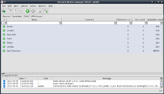
Figure 6-17 The mdm main window with pool table
Pool table columns
The pool overview table contains the following columns.
Pool table columns |
||
|---|---|---|
|
Status (S) |
The status icon shows whether the pool definition is valid. |
|
Name |
The name assigned to the pool. |
|
Comment |
Optional comment. |
|
Reference count |
This column shows how many variables reference this pool (see “Pool properties dialog” on page 113). |
|
Use count |
This column shows how many values have been used from the pool (see “Pool properties dialog” on page 113). |
|
Available count |
This number shows how many values are still available in the pool (see “Pool properties dialog” on page 113). |
Filtering and sorting the table
The header of the table can be used to sort the table entries. A click on a header of a column will activate the (primary) sort based on this column. This is indicated by the arrow in the column header. A second click on the same header will reverse the sort order. Clicking on another column header activates the sort based on this new column, the previously activated column will be used as secondary sorting criterion.
The first row of the table accepts the input of regular expressions (please refer to Chapter 11, Regular expressions), which can be used to efficiently filter the table entries. Filtering based on regular expressions is not used for the column that does not contain text (i.e. column S).
The
filter criterion for the three count columns
is not interpreted as a regular expression, but as a comma-separated list
of numbers or number ranges
(e.g. 0,2-3).
The filter history will be saved for the current user and can be accessed using the drop down functionality of the filter fields.
Creating pools
There are several ways to create new pools:
1.Open the context menu by clicking on the pool table with the right mouse button. To open the Pool properties dialog for a new pool please select Add in the context menu.
2.Select
the Pool tab and click on the  icon
in the menu bar to open the Pool properties dialog
for a new pool.
icon
in the menu bar to open the Pool properties dialog
for a new pool.
3.Select New » Pool in the main menu to open the Pool properties dialog for a new pool.
Editing pools
There are several ways to edit a pool:
1.Double-click with the left mouse button on the pool in the table to open the Pool properties dialog.
2.Select the pool with the left mouse button and open the context menu by pressing the right mouse button. Then select Edit to open the Pool properties dialog.
3.Select the pool to be modified in the pool table. Select Edit » Edit Item in the main menu to open the Pool properties dialog.
Deleting pools
There are several methods to delete pools:
1.Select the pool(s) and open the context menu by clicking with the right mouse button. To delete the pools please select Delete in the context menu.
2.Select
the pools to be deleted in the pool table and click on the  icon
in the menu bar.
icon
in the menu bar.
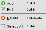
The following entries are available in the context menu of the pool overview table.
Pool context menu |
||
|---|---|---|
|
Add |
Create a new pool and open the Pool properties dialog of the new pool. |
|
Edit |
Edit the selected pool (only active if exactly one pool is selected in the overview table). |
|
Delete |
Delete the selected pools. |
|
Select All |
Select all pools not excluded by the table filter. |
The Pool properties dialog allows to define value pools, which can be used to automatically configure certain variables (e.g. the virtual address for VPNs). Currently mdm allows to define address range pools (CIDR notation), see below for an example.
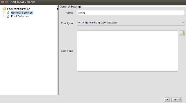
Figure 6-18 Pool properties dialog
General settings
The entry General settings contains the following parameters for the pool:
Pool properties dialog |
||
|---|---|---|
General settings |
Name |
A name for the pool. This name will be used when referencing the pool in a variable (see section Pool values usage in variables below). |
|
Pool type |
Currently only the pool type IP Networks in CIDR Notation is available. |
|
Comment |
A comment (optional). |
Pool definition
The entry Pool Definition allows to define the value range of the pool and the address range of the values to be taken out of the pool. Figure 6-19 contains an example of a pool definition.

Figure 6-19 Definition of a CIDR pool
The CIDR pool in the example contains all addresses defined in the table Network List. The field Network Mask defines the range of single values to be taken out of the pool, i.e. when using this pool in a variable, mdm will automatically assign an IP address range with a mask of 24 out of the available Source Networks to that variable.
E.g. if the pool is used for the template variable Remote network (in a VPN connection), then mdm will automatically assign a value to the variable Remote network of all devices using the respective template. The pool overview table in the main window shows how many values have been taken out of the pool (Use count) and how many values are still available in the pool (Available count).
Please note that once defined, it is not possible to change or delete the source address ranges and the network mask in the pool any more, e.g. it is not possible to decrease the network range 10.12.0.0/16 to 10.12.0.0/19 in the example above. It is only possible to add further ranges to the pool, i.e. increase the pool value range. Please carefully plan the definition of the pool ranges in advance. |
Pool value usage in variables
Pool values can only be used in templates. For certain variables you can choose the pool you would like to use from the drop down box, e.g. in Figure 6-20 a number of pools (London, New York, Paris, etc.) are available to be used for the variable IP of external interface. Only pools that match the variable type (e.g. CIDR pool and variable of type IP address) are shown in the drop down box. If a pool is used in a template, no value is assigned to the respective variable, the pool is only referenced at this point. Therefore the Reference count in the pool table will be increased by one. If a value is assigned to a variable (which happens on device level, not on template level) the Use count is increased by one.
This assignment happens automatically if you edit an inherited template of a device by referencing a pool from a variable to the template or if you assign a template to a device that already references a pool.
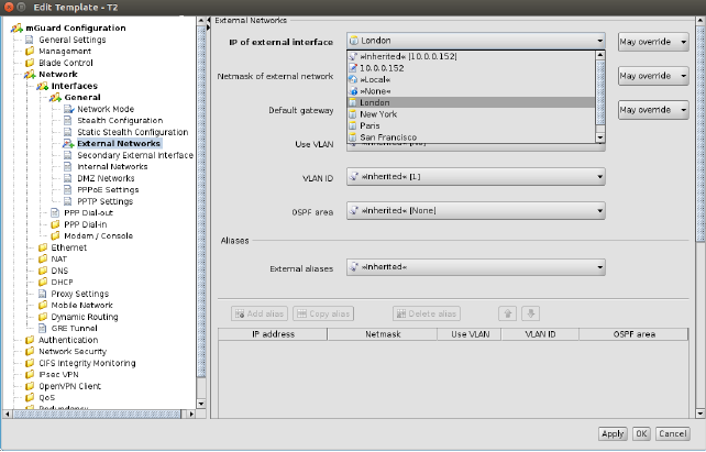
Figure 6-20 Usage of pool values
The following should be kept in mind when working with pools.
In a variable that requires an IP address (not an IP network) only pools with a network mask of 32 can be referenced. |
If you decide to override a pool value in a device, the assigned pool value is not returned to the pool (i.e. the use count is not decreased), but remains assigned “in the background”, in case you decide to use the inherited value again. |
Pools must be large enough to provide a value for every device that inherits from the template in which the pool is referenced, even if some of the devices override their respective pool value (see above). |
Please select the VPN Groups tab to access the VPN group overview table. A VPN group is used to group devices into a meshed VPN network. For detailed information on VPN groups and their usage please refer to “VPN group properties dialog (Meshed VPN networks)” on page 124.
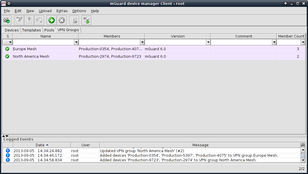
Figure 6-21 The mdm main window with VPN group table
VPN group table columns
The VPN group overview table contains the following columns
.
The column width can be changed by placing the cursor on the header of the table at the border of two columns and dragging the border to the desired location. The order of the columns can be changed by dragging the column header to a different location. |
VPN group table columns |
||
|---|---|---|
|
Status (S) |
The status icon shows whether the VPN group is currently locked. |
|
Name |
The name assigned to the VPN group. The name can be set in the General Settings of the VPN group properties dialog (see Chapter 6.6.4). |
|
Members |
A comma-separated list of the devices which are members of the VPN group (i.e. which are a part of the meshed VPN network defined by the VPN group). |
|
Version |
The mGuard firmware version that is used for the VPN group. |
|
Comment |
Optional comment. The comment can be set in the General Settings of the VPN group properties dialog (see Chapter 6.6.4). |
|
Member Count |
This column shows the number of devices which are members of the VPN group. |
Filtering and sorting the table
The header of the table can be used to sort the table entries. A click on a header of a column will activate the (primary) sort based on this column. This is indicated by the arrow in the column header. A second click on the same header will reverse the sort order. Clicking on another column header activates the sort based on this new column, the previously activated column will be used as secondary sorting criterion.
The first row of the table accepts the input of regular expressions (please refer to Chapter 11, Regular expressions), which can be used to efficiently filter the table entries. Filtering based on regular expressions is not used for the column that does not contain text (i.e. column S).
The filter criterion for the Member Count column is not interpreted as a regular expression, but as a comma-separated list of numbers or number ranges (e.g. 0,2–3).
The filter history will be saved for the current user and can be accessed using the drop down functionality of the filter fields.
Creating VPN groups
There are several ways to create new VPN groups:
1.Open the context menu by clicking on the VPN group table with the right mouse button. To open the VPN group properties dialog for a new VPN group please select Add in the context menu.
2.Select
the VPN Group tab and click on the  icon
in the menu bar to open the VPN group properties dialog
for a new VPN group.
icon
in the menu bar to open the VPN group properties dialog
for a new VPN group.
3.Select New » VPN Group in the main menu to open the VPN group properties dialog for a new VPN group.
Editing VPN groups
There are several ways to edit a VPN group:
1.Double-click with the left mouse button on the VPN group in the table to open the VPN group properties dialog.
2.Select the VPN group with the left mouse button and open the context menu by pressing the right mouse button. Then select Edit to open the VPN group properties dialog.
3.Select the device to be modified in the device table. Select Edit » Edit Item in the main menu to open the VPN group properties dialog.
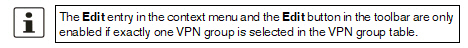
Deleting VPN groups
There are several methods to delete VPN groups:
1.Select the VPN group(s) in the VPN group table and open the context menu by clicking with the right mouse button. To delete the VPN groups please select Delete in the context menu.
2.Select
the VPN groups to be deleted in the table and click on the  icon
in the menu bar.
icon
in the menu bar.
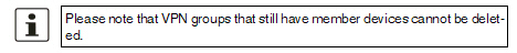
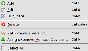
The following entries are available in the context menu of the VPN group overview table.
VPN group context menu |
||
|---|---|---|
|
Add |
Create a new VPN group and open the VPN group properties dialog of the new VPN group. |
|
Edit |
Edit the selected VPN group (only active if exactly one VPN group is selected in the overview table). |
|
Duplicate |
To create a duplicate of a VPN group please open the context menu by clicking with the right mouse button on the VPN group in the VPN group table. Select Duplicate in the context menu. mdm will create a copy of the VPN group and append the string _copy<n> (<n> is a number) to the name of the new VPN group. Please note that the Duplicate menu entry is only enabled if exactly one VPN group is selected in the VPN group table. |
|
Delete |
Delete the selected VPN groups. |
|
Set Firmware Version
|
Since different firmware versions of the mGuard software have different sets of variables, the firmware version corresponding to the installed firmware on the mGuard has to be selected here. 
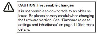
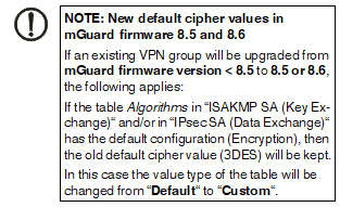

|
|
Assign/Remove Member Devices |
Edit member devices of one or more VPN groups. Please refer to “Editing device membership in VPN groups” on page 122 for more details. |
|
Select All |
Select all VPN groups not excluded by the table filter. |
6.6.3Editing device membership in VPN groups
When Assign/Remove Member Devices in the VPN group context menu is activated, a dialog opens to edit the device membership of the selected VPN groups:
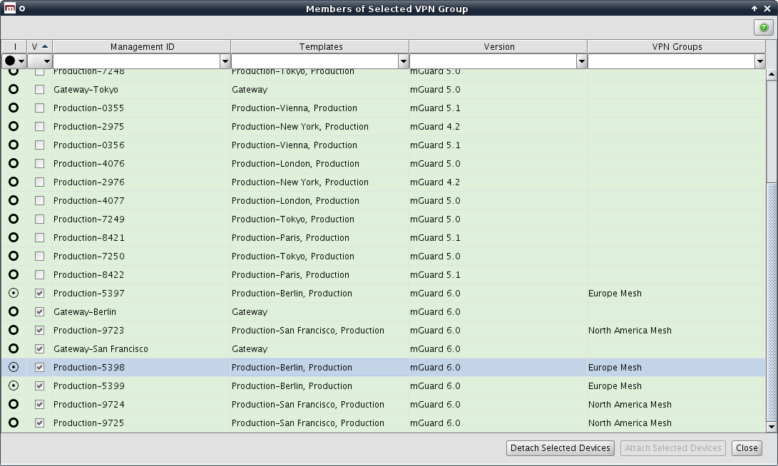
Figure 6-22 The dialog to edit device membership in VPN groups
VPN group membership table columns
The VPN group membership table contains the following columns.
The column width can be changed by placing the cursor on the header of the table at the border of two columns and dragging the border to the desired location. The order of the columns can be changed by dragging the column header to a different location. |
VPN group membership table columns |
||
|---|---|---|
|
Status I |
The I status
icon indicates whether a device is a member of none, some, or
all of the selected VPN groups. Click on the |
|
Status V |
The V status icon shows whether the firmware version of the device is compatible with (i.e. equal to or newer than) the firmware version of the selected VPN groups. |
|
Management ID |
The Management ID of the device. |
|
Templates |
A comma-separated list of the device’s ancestor templates. The first item in the list is the immediate parent template. |
|
Version |
The firmware version of the VPN group. |
|
VPN Groups |
A comma-separated list of VPN groups that the device is currently a member of. |
Filtering and sorting the table
The header of the table can be used to sort the table entries. A click on a header of a column will activate the (primary) sort based on this column. This is indicated by the arrow in the column header. A second click on the same header will reverse the sort order. Clicking on another column header activates the sort based on this new column, the previously activated column will be used as secondary sorting criterion.
The first row of the table accepts the input of regular expressions (please refer to Chapter 11, Regular expressions), which can be used to efficiently filter the table entries. Filtering based on regular expressions is not used for the columns that do not contain text (i.e. columns I and V).
Selecting devices
Select the device(s) for which to modify the VPN group membership:
–Click on a device to select it.
–Click on a device, then hold down the Shift key and click on a second device to select a range of devices.
–Click on a device while holding down the Ctrl key to toggle its selection state.
Assigning or removing VPN group membership
Click on the Attach Selected Devices button to make the selected devices members of the selected VPN groups (i.e. the VPN groups that were selected in the VPN group table when the dialog was opened). Likewise, click on the Detach Selected Devices button to revoke the membership of the selected devices from the selected VPN groups.
A device can only be a member of a VPN group if the device’s firmware version is equal to or newer than the firmware version of the VPN group. |
Any attempt to add a device to a VPN group of which it is already a member, or to remove a device from a VPN group of which it is not a member, is ignored. |
Devices are added to or removed from VPN groups in the background. The dialog can be closed while the operation is still being performed. |
6.6.4VPN group properties dialog (Meshed VPN networks)
The member devices of a VPN group form a meshed VPN network: For each member device, mdm generates a VPN connection (referred to as a VPN group connection) to every other member device. A device can be a member of multiple VPN groups. If this results in multiple VPN connections between the same two devices, mdm generates only one such connection. VPN groups are not available for firmware versions earlier than 6.0.
The VPN group properties dialog allows to configure common variables used in all VPN connections within the group.
For information on how to create, delete or edit VPN groups, and how to add or remove member devices, please refer to “VPN group overview table” on page 117.
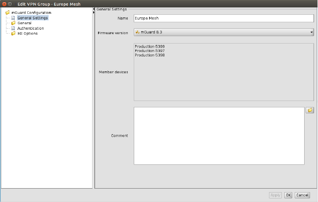
Figure 6-23 VPN group properties dialog
Similar to the Device and Template properties dialogs the VPN group properties dialog contains a navigation tree on the left side. It allows you to conveniently navigate to each variable.
General settings
The VPN group properties dialog contains the entry General settings for the configuration of additional parameters related to mdm. The following parameters can be set in the General settings.
VPN group properties dialog (Meshed VPN networks) |
||
|---|---|---|
General settings |
Name |
The name is used to identify the VPN group within mdm. It must be unique. |
|
Firmware Version |
Since different firmware versions of the mGuard software have different sets of variables, the firmware version corresponding to the installed firmware on the mGuard has to be selected here. 

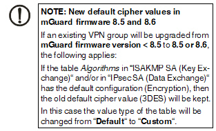

|
|
Member devices (read only) |
The devices which are currently members of the VPN group. |
|
Comment |
An optional comment. |
VPN group connections
When generating VPN group connections, mdm combines the variables in the VPN group with additional variables in the device. While the variables in the VPN group are common to all connections in this group, the additional variables in the device are specific to the device, but common to all VPN group connections of the device.
The VPN group contains the following variables:
–General VPN settings
–Protocol settings
–Authentication settings
–IKE options
Devices and templates contain variables under the IPsec VPN » VPN Group Configuration node which are used when mdm adds VPN group connections to a device:
–Tunnel settings
–NAT settings
–Firewall settings
The local VPN network
The local VPN network to be used in VPN group connections can either be specified in the template or device (IPsec VPN » VPN Group Configuration » Tunnel Settings » Local), or, if the device is operated in router mode, it can be automatically derived. If the IPsec VPN » VPN Group Configuration » Tunnel Settings » Use first internal address as local VPN network in router mode variable is set to Yes, mdm uses the first internal address and associated netmask, so that the corresponding local network is visible through the VPN tunnel. The setting has no effect in stealth mode, i.e. if the device is operated in stealth mode, the local VPN network must always be specified.
Local 1:1 NAT
VPN group connections can be configured to perform 1:1 NAT on local addresses. None of the other NAT mechanisms for VPN connections are available in VPN group connections.
Local 1:1 NAT is enabled by setting the IPsec VPN » VPN Group Configuration » NAT » Enable 1:1 NAT of local addresses variable to Yes. The local network within the tunnel must be specified.
Please note that the network within the tunnel (i.e. the network addresses as seen by the peer) is specified in the 1:1 NAT settings. This is different from the mGuard Web GUI where the network outside of the tunnel (i.e. the network addresses as seen from the local network) is specified in the 1:1 NAT settings. |
Extended firewall rules
The firewall rules under the IPsec VPN » VPN Group Configuration node contain additonal Combine fields associated with the From IP and To IP addresses or networks. If a Combine field is set to No, the corresponding address or network is used in the VPN group connection without modification.
If a Combine field is set to Yes, the address or network entered in the table is combined with the local or remote VPN network to calculate the network used in the VPN group connection.
–In the incoming firewall rules, the From IP field is combined with the remote VPN network and the To IP field is combined with the local VNP network.
–In the outgoing firewall rules, the From IP field is combined with the local VPN network and the To IP field is combined with the remote VNP network.
The value of the From IP or To IP field is combined with the VPN network by adding the addresses octet-wise, i.e. each octet is added individually. If the result of adding two octets overflows (i.e if it is greater than 255), the value 256 is subtracted (i.e. the addition “wraps around”). The network mask of the value of the From IP or To IP field (or 32 if the field does not contain a network mask) is applied to the result.
Examples:
–If the From IP or To IP field has the value 0.0.78.0/24, and the VPN network is 10.6.0.0/16, the combined value is 10.6.78.0/24.
–If the From IP or To IP field has the value 0.1.78.0/24, and the VPN network is 10.6.0.0/16, the combined value is 10.7.78.0/24.
With mdm you can easily generate the configuration for a large number of VPN tunnels. In general, the information contained in Chapter 6.1, Chapter 6.3.3, Chapter 6.4.3 and Chapter 6.4.5 applies also to the VPN configuration.
But VPNs require some special settings to be taken into consideration, which are explained in this chapter, e.g. the automatic configuration of the VPN peer. You can find the VPN configuration in the node IPsec VPN of the navigation tree.
Adding and editing VPN connections
To add, change or delete VPN connections, please open the node IPsec VPN » Connections. To create a new connection, create a new table row (see “Modifying mGuard table variables” on page 67). As soon as you create a connection, it appears as node in the navigation tree. To edit the connection, open its node in the navigation tree and navigate to the desired settings. The structure of the connection node resembles the menu structure on the mGuard.
The connection table is read-only, i.e. you have to navigate to the respective node to make changes to the connection, e.g. change the name of the connection or disable a connection. |
Please note that the permission setting of the connection table in a template applies to the table only, and not to the contents of the connections. If you set the table to No override, the settings of the VPN connection can still be modified on a device which uses this template, but the user on the device level is not allowed to add further connections to the table. |
Automatic configuration of the VPN peer
You can automatically generate the VPN configuration for the peer device (see Figure 6-24): Place the cursor in the field Peer device and press the Cursor Down key. A list of available devices appears. You can limit the number of devices in the list by entering the first characters of the Management ID of the desired device. If you select a device, the VPN configuration for this device will be automatically generated.
Not all settings of the peer can be automatically generated, therefore you have to enter parts of the configuration manually. Please check the sub-nodes of the VPN connection for those settings, they are in the relevant subnodes separated from the other settings by the text Configuration of peer device (for an example see Figure 6-24). |
The automatically generated VPN connections show up as read-only in the peer connection table, i.e. you cannot change the configuraton on the peer side. |
If the VPN gateways have different firmware versions the configuration of a peer is only possible in the Properties Dialog of the device with the older firmware version. If you configure the peer in the Properties Dialog of the device with newer firmware the connection will not be generated in the device with the older firmware. There will be no error or warning displayed. |
The automatically generated VPN connections can be used as alternative to the mGuard Tunnel Group feature (mGuard 5.0 or later), see comments in section Hints for VPN configurations below. |
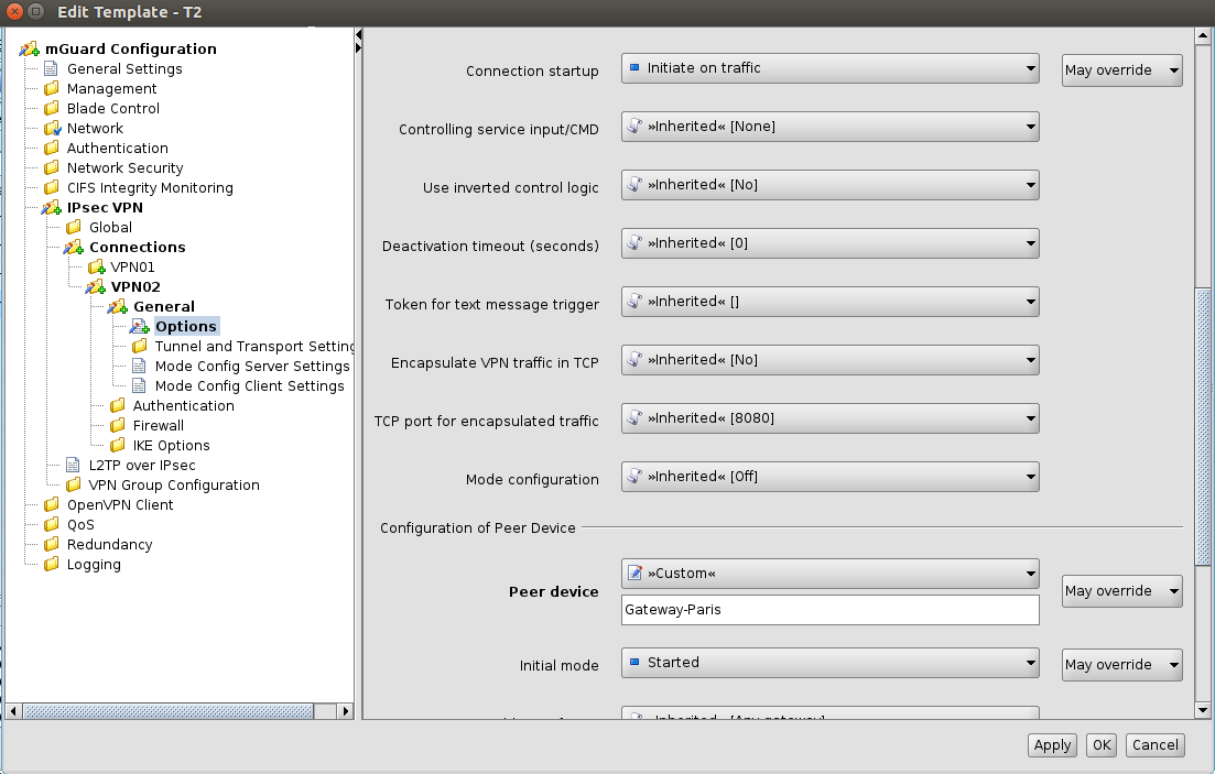
Figure 6-24 Automatic configuration of VPN peer
Setting VPN identifiers automatically
The local and the remote machine certificate are known to mdm in many typical usage scenarios (when VPN configuration for the peer device is generated by mdm). mdm can make use of this information to set the Local VPN Identifier and the Remote VPN Identifier variables automatically, i.e. derive the identifiers from the known certificates. It is necessary to set these variables when CA certificates are used to authenticate VPN connections.
To make use of this feature, open the IPsec VPN » Connections » Connection Name » Authentication » VPN Identifiers node and set the variable Set VPN Identifiers automatically to yes. In this mode, the Local VPN Identifier and the Remote VPN Identifier variables are ignored; the identifiers are derived from the cerificates.
Copying firewall rules
The firewall tables within VPN connections contain a Copy from Main button. Clicking this button copies the content of the corresponding firewall table for non-VPN traffic (i.e. if the current firewall table is for incoming traffic, the incoming firewall table for non-VPN traffic is copied; likewise for outgoing traffic).
A separate background color is used to indicate which firewall rules have been copied. The background color is cleared once a different navigation tree node is opened.
Hints for VPN configurations
These hints are useful if the tunnel group feature is not used and the VPN connections are explicitly defined.
In 1:N VPN configurations it is recommended to define the VPN connection in a template and select the central device in the Peer device field (See section Automatic configuration of peer above). If you assign this template to the devices mdm will automatically generate the N connection configurations for the central device. |
In a 1:N VPN configuration it is required for the configuration of the peer to specify the gateway address of the current device (see Figure 6-24, Configuration of peer device » Gateway address of peer). If certificates are used %any (as shown in Figure 6-24) can be used as address in the template, but if PSK authentication is used, %any is not allowed. If PSK authentication is used, the external address (if no NAT us used) has to be entered into the field Configuration of peer device » Gateway address of peer for each device. |


 icon in front of the variable name
in the
icon in front of the variable name
in the  icon in front of the variable
name. In the example the value from the template is overridden
with a custom value.
icon in front of the variable
name. In the example the value from the template is overridden
with a custom value. icon in front of the variable
name. In this example the value from the template is overridden
in the device configuration with a custom value.
icon in front of the variable
name. In this example the value from the template is overridden
in the device configuration with a custom value. icon
in front of the variable name and the blue-colored label. If a
device for which None values have not been assigned is uploaded,
an error occurs.
icon
in front of the variable name and the blue-colored label. If a
device for which None values have not been assigned is uploaded,
an error occurs.


 icon
to open a dialog which explains the available icons and their
meanings.
icon
to open a dialog which explains the available icons and their
meanings.


