
The OpenVPN client supports the following TLS versions: TLS 1.0, TLS 1.1, TLS 1.2, and TLS 1.3.
9.1OpenVPN Client >> Connections
With OpenVPN, an encrypted VPN connection can be established between the mGuard as the OpenVPN client and a peer (OpenVPN server). The OpenSSL library is used for encryption and authentication. Data is transported using the TCP or UDP protocols.
|
The OpenVPN client supports the following TLS versions: TLS 1.0, TLS 1.1, TLS 1.2, and TLS 1.3. |
|
For security reasons, select versions TLS 1.2 or 1.3 as the “Lowest supported TLS version” to ensure secure TLS-encrypted connections. |
Requirements for a VPN connection
A general requirement for a VPN connection is that the IP addresses of the VPN peers are known and can be accessed.
–mGuard devices provided in stealth network mode are preset to the “multiple clients” stealth configuration. In this mode, you need to configure a management IP address and default gateway if you want to use VPN connections (see “Default gateway” on page 140). Alternatively, you can select a different stealth configuration than the “multiple clients” configuration or use another network mode.
–In order to successfully establish an OpenVPN connection, the VPN peer must support the OpenVPN protocol as the OpenVPN server.
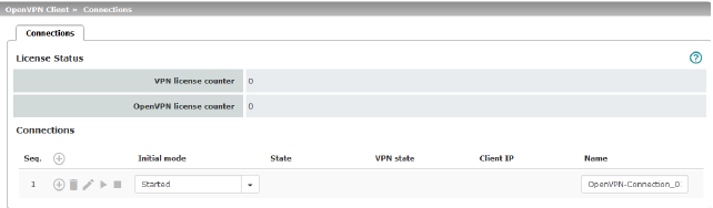
Lists all the VPN connections that have been defined.
Each connection name listed here can refer to an individual VPN connection. You also have the option of defining new VPN connections, activating and deactivating VPN connections, changing (editing) the VPN connection properties, and deleting connections.
|
OpenVPN Client >> Connections |
||
|---|---|---|
|
License Status |
VPN license counter |
Number of peers that currently have a VPN connection established using the IPsec protocol. |
|
|
OpenVPN license counter |
Number of peers to which a VPN connection is currently established using the OpenVPN protocol. |
|
Connections |
Initial mode |
Disabled / Stopped / Started The “Disabled” setting deactivates the VPN connection permanently; it cannot be started or stopped. The “Started” and “Stopped” settings determine the status of the VPN connection after restarting/booting the mGuard (e.g., after an interruption in the power supply). VPN connections that are not disabled can be started or stopped via icons on the web interface, via text message, a switch or a pushbutton. |
|
|
State |
Indicates the current activation state of the OpenVPN connection. |
|
|
VPN state |
Indicates whether or not the corresponding OpenVPN connection has been established. |
|
|
Client IP |
IP address of the OpenVPN interface. |
|
|
Name |
Name of the VPN connection |
Defining a new VPN connection
•In the connection table, click on the  Insert Row icon to add a new table row.
•Click on the  Edit Row icon.
Editing a VPN connection
Click on the  Edit Row icon in the relevant row.
.
|
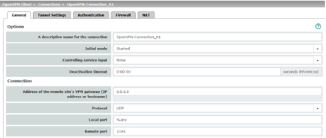
Options |
The connection can be freely named/renamed. |
|
|
|
Initial mode |
Disabled / Stopped / Started The “Disabled” setting deactivates the VPN connection permanently; it cannot be started or stopped. The “Started” and “Stopped” settings determine the status of the VPN connection after restarting/booting the mGuard (e.g., after an interruption in the power supply). VPN connections that are not disabled can be started or stopped via icons on the web interface, via text message, a switch or a pushbutton. |
|
|
Controlling service input
|
None / Service input CMD 1-3 (I 1-3) The VPN connection can be switched via a connected pushbutton/switch. The pushbutton/switch must be connected to one of the service contacts (CMD 1-3). 
|
|
|
Use inverted control logic |
Inverts the behavior of the connected switch. If the switching service input is configured as an on/off switch, it can activate one VPN connection while simultaneously deactivating another which uses inverted logic, for example. |
|
|
Deactivation timeout |
Time, after which the VPN connection is stopped, if it has been started via switch, pushbutton or the web interface. The timeout starts on transition to the “Started” state. After the timeout has elapsed, the connection remains in the “Stopped” state until it is restarted. Time in hours, minutes and/or seconds (00:00:00 to 720:00:00, around 1 month). The entry can be in seconds [ss], minutes and seconds [mm:ss] or hours, minutes, and seconds [hh:mm:ss]. 0 means the setting is disabled. |
|
Connection |
Address of the remote site's VPN gateway |
IP address or host name of the VPN gateway of the peer |
|
|
Protocol |
TCP / UDP The network protocol used by the OpenVPN server must likewise be selected here in the mGuard. |
|
|
Local port |
The port of the local OpenVPN client from which the connection to an OpenVPN server is initiated. Values: 1 - 65535; default: %any (selection left to the peer) |
|
|
Remote port |
Port on the remote OpenVPN server that should respond to requests from the OpenVPN client. Values: 1 - 65535; default: 1194 |
|
OpenVPN Client >> Connections >> Edit >> Tunnel Settings |
||
|
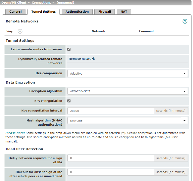
Remote Networks |
Network |
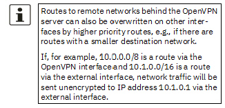
Addresses of networks that are located behind the OpenVPN server (VPN gateway of the peer) (CIDR format). |
|
|
Comment |
Optional comment text. |
|
Tunnel Settings |
Learn remote routes from server |
When the function is activated (default), remote networks are automatically learned from the server if the server is configured accordingly. 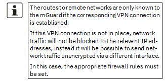
When the function is deactivated, the statically entered routes will be used. |
|
|
Dynamically learned remote networks |
Dynamically learned remote networks are displayed. |
|
|
Use compression |
Yes / No / Adaptive / Disabled You can select whether compression should always be applied, should never be applied or should be applied adaptively (adapted according to the type of traffic). The option Disabled disables compression completely by disabling the use of liblzo resp. comp-lzo. 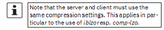
|
|
Data Encryption |
Encryption algorithm |
AES-128-CBC* / AES-192-CBC* / AES-256-CBC / Decide on which encryption algorithm should be used with the administrator of the peer. 
The following generally applies: the longer the key length (in bits) used by an encryption algorithm (specified by the appended number), the more secure it is. The longer the key, the more time-consuming the encryption procedure. |
|
|
Hash algorithm |
SHA-1*, SHA-256 (default), SHA-512 Hash algorithm for calculating the checksum used to secure the encrypted OpenVPN connection between the OpenVPN server and mGuard client. 
|
|
|
Key renegotiation |
When the function is activated (default), the mGuard will attempt to negotiate a new key when the old one expires. |
|
|
Key renegotiation interval |
Duration after which the validity of the current key expires and a new key is negotiated between the server and client. Time in hh:mm:ss (default: 8 h) |
|
Dead Peer Detection |
If the peer supports Dead Peer Detection, the relevant partners can detect whether the OpenVPN connection is still active or whether it needs to be established again. |
|
|
|
Delay between requests for a sign of life |
Duration after which DPD Keep Alive requests should be transmitted. These requests test whether the peer is still available. Time in hh:mm:ss Default: 00:00:00 (DPD is disabled) |
|
|
Timeout for absent sign of life after which peer is assumed dead |
Duration after which the connection to the peer should be declared dead if there has been no response to the Keep Alive requests. Time in hh:mm:ss 
Default: 00:00:00 (DPD is disabled) |
|
OpenVPN Client >> Connections >> Edit >> Authentication |
||
|---|---|---|
|
Authentication |
Authentication method |
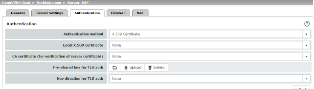
There are three ways in which the mGuard can authenticate itself as an OpenVPN client to the OpenVPN server: –X.509 Certificate (default) –Login/password –X.509 Certificate + login/password The page contains different setting options depending on the method chosen. |
|
|
Login |
Authentication method: Login/Password User identifier (login) that the mGuard uses to authenticate itself to the OpenVPN server. |
|
|
Password |
Agreed password that is used together with a user identifier (login) for authentication. 
|
|
|
|
Authentication method: X.509 Certificate Each VPN device has a secret private key and a public key in the form of an X.509 certificate, which contains further information about the certificate's owner and the certification authority (CA). The following must be specified: –How the mGuard authenticates itself to the peer –How the mGuard authenticates the remote peer |
|
|
Local X.509 certificate |
Specifies which machine certificate the mGuard uses as authentication to the VPN peer. Select one of the machine certificates from the selection list. The selection list contains the machine certificates that have been loaded on the mGuard under the “Authentication >> Certificates” menu item. 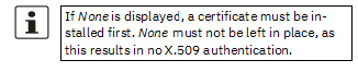
|
|
|
CA certificate (for verification of server certificate) |
Only the CA certificate from the certification authority (CA) that signed the certificate shown by the VPN peer (OpenVPN server) should be referenced here (selection from list). 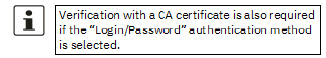
The additional CA certificates that form the chain to the root CA certificate together with the certificate shown by the peer must then be imported into the mGuard under the “Authentication >> Certificates” menu item. 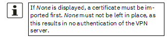
The selection list contains all CA certificates that have been imported into the mGuard under the “Authentication >> Certificates” menu item. With this setting, all VPN peers are accepted, providing they log in with a signed CA certificate issued by a recognized certification authority (CA). The CA is recognized if the relevant CA certificate and all other CA certificates have been loaded on the mGuard. These then form the chain to the root certificate together with the certificates shown. |
|
|
Pre-shared key for TLS auth |
To increase security (e.g., prevent DoS attacks), authentication of the OpenVPN connection can also be protected via pre-shared keys (TLS-PSK). To do so, first a static PSK file (e.g., ta.key) must be created and installed and activated on both OpenVPN peers (server and client). The PSK file can: –be created by the OpenVPN server or –consist of any file (8 – 2048 bytes). If the file is generated by the server, the key direction can also be selected (see below). To activate TLS authentication, a PSK file must be selected using the To deactivate TLS authentication, the file must be deleted using the Delete button. The Delete button is always visible, i.e., even if no PSK file has been uploaded or an uploaded PSK file has been deleted. |
|
|
Key direction for TLS auth |
None / 0 / 1 None Must be selected if the PSK file was not generated by the OpenVPN server. 0 and 1 Can be selected if the PSK file was generated by the OpenVPN server. The selection on the client and server side must be complementary (0 <–>1 or 1 <–> 0) or identical (None <–> None). If the settings are incorrect, the connection will not be established and a log entry will be generated. |
Incoming/outgoing firewall
While the settings made under the Network Security menu item only relate to non-VPN connections (see above under “Network Security menu” on page 201), the settings here only relate to the VPN connection defined on these tabs.
If multiple VPN connections have been defined, you can restrict the outgoing or incoming access individually for each connection. Any attempts to bypass these restrictions can be logged.
|
By default, the VPN firewall is set to allow all connections for this VPN connection. However, the extended firewall settings defined and explained above apply independently for each individual VPN connection (see “Network Security menu” on page 201, “Network Security >> Packet Filter” on page 201, “Advanced” on page 221). |
|
If multiple firewall rules are defined, these are queried starting from the top of the list of entries until an appropriate rule is found. This rule is then applied. If the list of rules contains further subsequent rules that could also apply, these rules are ignored. |
|
In Single Stealth mode, the actual IP address used by the client should be used in the firewall rules, or it should be left at 0.0.0.0/0, as only one client can be addressed through the tunnel. |
|
If the Allow packet forwarding between VPN connections function is activated on the Options tab under the IPsec VPN >> Global menu item, the rules under Incoming are used for the incoming data packets to the mGuard, and the rules under Outgoing are applied to the outgoing data packets. This applies for OpenVPN connections as well as for IPsec connections. If the outgoing data packets are included in the same connection definition, then the firewall rules for Incoming and Outgoing for the same connection definition are used. If a different VPN connection definition applies to the outgoing data packets, the firewall rules for Outgoing for this other connection definition are used. |
|
If the mGuard has been configured to forward SSH connection packets (e.g., by permitting a SEC-Stick hub & spoke connection), existing VPN firewall rules are not applied. This means, for example, that packets of an SSH connection are sent through a VPN tunnel despite the fact that this is prohibited by its firewall rules. |
|
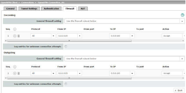
Incoming |
General firewall setting |
Accept all incoming connections: the data packets of all incoming connections are allowed. Drop all incoming connections: the data packets of all incoming connections are discarded. Accept Ping only: the data packets of all incoming connections are discarded, except for ping packets (ICMP). Use the firewall ruleset below: displays further setting options. |
|
|
The following settings are only visible if “Use the firewall ruleset below” is set. |
|
|
|
Protocol |
All means TCP, UDP, ICMP, GRE, and other IP protocols. |
|
|
From IP/To IP |
0.0.0.0/0 means all IP addresses. To specify an address area, use CIDR format (see “CIDR (Classless Inter-Domain Routing)” on page 41). Name of IP groups, if defined. When a name is specified for an IP group, the host names, IP addresses, IP areas or networks saved under this name are taken into consideration (see “IP/Port Groups” on page 218). 
Incoming: –From IP: IP address in the VPN tunnel –To IP: 1:1 NAT address or the actual address Outgoing: –From IP: 1:1 NAT address or the actual address –To IP: IP address in the VPN tunnel |
|
|
From port / To port (Only for TCP and UDP protocols) |
any refers to any port. startport:endport (e.g., 110:120) refers to a port range. Individual ports can be specified using the port number or the corresponding service name (e.g., 110 for pop3 or pop3 for 110). Name of port groups, if defined. When a name is specified for a port group, the ports or port ranges saved under this name are taken into consideration (see “IP/Port Groups” on page 218). |
|
|
Action |
Accept means that the data packets may pass through. Reject means that the data packets are sent back and the sender is informed of their rejection. (In Stealth mode, Reject has the same effect as Drop.) Drop means that the data packets are not permitted to pass through. They are discarded, which means that the sender is not informed of their whereabouts. Name of rule records, if defined. When a name is specified for rule records, the firewall rules configured under this name take effect (see “Rule Records” tab). 

Name of Modbus TCP rule records, if defined. |
|
|
Freely selectable comment for this rule. |
|
|
|
Log |
For each individual firewall rule, you can specify whether the use of the rule: –Should be logged – activate Log function –Should not be logged – deactivate Log function (default) |
|
|
Log entries for unknown connection attempts |
When the function is activated, all connection attempts that are not covered by the rules defined above are logged. |
|
Outgoing |
The explanation provided under “Incoming” also applies to “Outgoing”. |
|
The IP address (OpenVPN client IP address) that the mGuard uses as the OpenVPN client is assigned to it by the OpenVPN server of the peer.
If NAT is not used, the local networks of the mGuard, from which the OpenVPN connection should be used, must be statically configured in the OpenVPN server. It is therefore recommended that you use NAT, i.e., that local routes (local IP addresses within the private address area) are rewritten to the OpenVPN client IP address so that devices in the local network can use the OpenVPN connection.
|
Local NAT |
For outgoing data packets, the device can rewrite the specified sender IP addresses from its internal network to its OpenVPN client IP address, a technique referred to as NAT (Network Address Translation). This method is used if the internal addresses cannot or should not be routed externally, e.g., because a private address area such as 192.168.x.x or the internal network structure should be hidden. 
|
|
|
|
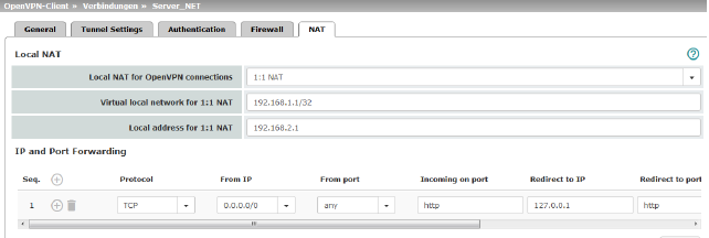
Local NAT for OpenVPN connections |
No NAT / 1:1 NAT / Masquerade It is possible to translate the IP addresses of devices located at the local end of the OpenVPN tunnel, (e.g., behind the mGuard). No NAT: NAT is not performed. With 1:1 NAT, the IP addresses of devices at the local end of the tunnel are exchanged so that each individual address is translated into another specific address. With Masquerade, the IP addresses of devices at the local end of the tunnel are exchanged with an IP address that is identical for all devices. |
|
|
Virtual local network for 1:1 NAT (When “1:1 NAT” was selected) |
Configures the virtual IP address area to which the actual local IP addresses are translated when 1:1 NAT is used. The netmask specified in CIDR format also applies to the Local address for 1:1-NAT (see below). 
|
|
|
Local address for 1:1-NAT (When “1:1 NAT” was selected) |
Configures the local IP address area from which IP addresses are translated into the virtual IP addresses through the use of 1:1-NAT in the Virtual local network for 1:1-NAT defined above (see above). The netmask specified for the Virtual local network for 1:1-NAT applies (see above). |
|
|
Network (When “Masquerading” was selected) |
Internal networks whose device IP addresses are translated into the OpenVPN client IP address. 0.0.0.0/0 means that all internal IP addresses are subject to the NAT procedure. To specify an address area, use CIDR format (see “CIDR (Classless Inter-Domain Routing)” on page 41). 
|
|
|
Comment |
Freely selectable comment for this rule. |
|
IP and Port Forwarding |
Lists the rules defined for IP and port forwarding (DNAT = Destination NAT). IP and port forwarding (DNAT) performs the following: the headers of incoming data packets from the OpenVPN tunnel, which are addressed to the OpenVPN client IP address of the mGuard and to a specific port of the mGuard, are rewritten in order to forward them to a specific computer in the internal network and to a specific port on this computer. In other words, the IP address and port number in the header of incoming data packets are changed. 
|
|
|
|
Protocol: TCP / UDP / GRE |
Specify the protocol to which the rule should apply (TCP / UDP / GRE). GRE protocol IP packets can be forwarded. However, only one GRE connection is supported at any given time. If more than one device sends GRE packets to the same external IP address, the mGuard may not be able to feed back reply packets correctly. 
|
|
|
From IP |
The sender address for forwarding. 0.0.0.0/0 means all addresses. To specify an address area, use CIDR format (see “CIDR (Classless Inter-Domain Routing)” on page 41). Name of IP groups, if defined. When a name is specified for an IP group, the host names, IP addresses, IP areas or networks saved under this name are taken into consideration (see “IP/Port Groups” on page 218). 
|
|
|
From port |
The sender port for forwarding. any refers to any port. Either the port number or the corresponding service name can be specified here, e.g., pop3 for port 110 or http for port 80. Name of port groups, if defined. When a name is specified for a port group, the ports or port ranges saved under this name are taken into consideration (see “IP/Port Groups” on page 218). |
|
|
Incoming on port |
The original destination port specified in the incoming data packets. Either the port number or the corresponding service name can be specified here, e.g., pop3 for port 110 or http for port 80. This information is not relevant for the “GRE” protocol. It is ignored by the mGuard. |
|
|
Redirect to IP |
The internal IP address to which the data packets should be forwarded and into which the original destination addresses are translated. |
|
|
Redirect to port |
Internal port to which the data packets should be forwarded and into which the original port is translated. |
|
|
Comment |
Freely selectable comment for this rule. |
|
|
Log |
For each individual port forwarding rule, you can specify whether the use of the rule: –Should be logged – activate Log function –Should not be logged – deactivate Log function (default) |

 icon and uploaded using the


