3Configuration help
3.1Secure
encryption
The mGuard
offers the option to use different encryption and hash algorithms.

Some of the available algorithms are
outdated and no longer considered secure. They are therefore not
recommended. However, they can still be selected and used for
reasons of downward compatibility. In the WBM, outdated algorithms
or unsecure settings are marked with an asterisk (*). |
In the following areas of the mGuard, the user must ensure that
secure encryption and hash algorithms are used:
–IPsec
VPN connections
–OpenVPN
connections
–Shell
Access (SSH)
–HTTPS
Web Access (TLS/SSL)
The secure use of encryption is explained
in the following sections.
Further information can be found for example
in the technical directive of the Federal office for information security:
“BSI TR-02102 Cryptographic procedure: recommendations and key lengths”.
Using
secure encryption and hash algorithms
Phoenix Contact recommends using encryption
and hash algorithms according to the following table.
Table 3-1 Secure encrpytion and hash
algorithms
Area
/ Protocol |
Encryption |
Hash
/ Checksum |
Diffie
Hellman / PFS |
VPN –
IPsec VPN |
ISAKMP SA (Key
Exchange) |
AES-256 |
SHA-256, -384, -512 |
2048 bits or higher |
IPsec SA (Data
Exchange) |
AES-256 |
SHA-256, -384, -512
|
|
Perfect Forward
Secrecy (PFS) |
|
|
2048 bits or higher |
VPN –
OpenVPN |
Data Encryption |
AES-256 -GCM |
SHA-256, -512 |
|
E-Mail
– SMTP |
Encryption mode
for the e-mail server |
TSL encryption , TLS encryption
with StartTLS |
TLS-based
encryption |
Lowest supported
TLS version |
TLS 1.3, TLS 1.2 |
Use of secure SSH clients
Establishing encrypted SSH connections to
the mGuard is initiated
by the SSH client used. If the SSH client uses outdated and thus insecure
encryption algorithms, these are generally accepted by the mGuard.

Always use Current
SSH clients (e.g. PuTTY),
to avoid use of weak encryption algorithms. |
Use of secure web browsers
Establishing encrypted HTTPS connections (TLS/SSL)
to the mGuard is initiated
by the web browser used. If the web browser uses outdated and thus insecure
encryption algorithms, these are only accepted by the mGuard if they
have been configured as the "Lowest supported TLS version“.

Always use up
to date web browsers or HTTPS clients to avoid use
of weak encryption algorithms. |

Select the version TLS 1.2 or TLS
1.3 as the "Lowest supported TLS version" on the mGuard
device. |
Creation of secure X.509 certificates
X.509 certificates are generated using various
software tools.

Always use up
to date program versions of the software tools to avoid
use of weak encryption algorithms when creating X.509 certificates.
|

When creating X.509 certificates,
use key lengths of at least 2048 bits and
secure hash algorithms (see
also Table 3-1). |
Use of X.509 certificates instead of Pre-Shared
Keys (PSK)
Pre-shared key (PSK) authentication in VPN
connections is considered insecure and should no longer be used. For security
reasons, use X.509 certificates for authentication.
Use of Configuration Pull (pull
config)

Select the version TLS 1.2 or TLS
1.3 as the "Lowest supported TLS version" on the mGuard
device. |
Use of Automatic
Update

Select the version TLS 1.2 or TLS
1.3 as the "Lowest supported TLS version" on the mGuard
device. |

Select the version TLS 1.2 or TLS
1.3 as the "Lowest supported TLS version" on the mGuard
device. |
Use of CRL
checking
3.2Suitable
web browsers
The device is configured via a graphic user
interface in the web browser.

Always use Current
web browsers to avoid use of weak encryption algorithms. |
Current versions of the following web browsers
are supported:
–Mozilla
Firefox
–Google
Chrome
–Microsoft
Edge
3.3Number
of concurrent sessions
Concurrent login to the web-based management
(WBM) of the device is limited to 10 web sessions (HTTPS). The limit applies
to the root, admin, audit, and netadmin users. The number
of concurrent logins of firewall users is not limited.
If 10 users are already logged in via the
HTTPS protocol, i.e. if 10 parallel web sessions have been started, the
device rejects the login of further users.

The limitation applies to logins via
the HTTPS protocol, regardless of the web client used. This includes
both web browsers and command line tools such as cURL. |

For security reasons and to avoid
blocking other users from logging in, users logged in via the
HTTPS protocol (web browser, cURL,
etc.) should always actively end their session after completing
their activity and log out of the device. |
Limitation of
login attempts
In the event of a Denial of Service attack,
services are intentionally made unable to function. To prevent this type
of attack, the mGuard is
provided with a throttle for different network requests.
This feature is used to count all the connections
going out from one IP address and using a specific protocol. When a certain
number of connection attempts is counted, the throttle becomes effective.
The throttle is reset if there are no further connection attempts for
30 seconds.
The number of connection attempts that lead
to activation of the throttle depends on the protocol used:
–32
when using HTTPS
–6
when using SSH, SNMP
3.4User
roles
root |
User role without restrictions |
admin |
Administrator |
netadmin |
Administrator for the network
only |
audit |
Auditor/tester |
The predefined users (root,
admin, netadmin,
audit) have different permissions.
–The
root user has unrestricted
access to the mGuard. The number of concurrent HTTPS sessions is limited.
–The
admin user has unrestricted
functional access to the mGuard.
The number of concurrent HTTPS sessions is limited. The number of simultaneous
SSH sessions can be restricted.
–Permissions
are explicitly assigned to the netadmin user
via the mGuard device manager (FL MGUARD DM UNLIMITED) . This user only has read access
to the other functions. Passwords and private keys cannot be read by this
user.
–The
audit user only has read
access to all functions. By default, the audit user
role can only be activated via the mGuard device manager (FL MGUARD DM UNLIMITED) , in the same way as netadmin.
3.5Input
help during configuration (system messages)
Modified or invalid entries are highlighted
in color in the web interface.
System messages which explain why an entry
is invalid, for example, are also displayed.

In order to support this, JavaScript
must be enabled in the web browser used. |
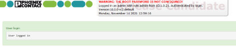
Figure 3-1Example system message
–Modified entries are highlighted in
green on the relevant page and in
the associated menu item until the changes are applied or reset. In the
case of tables, it is only indicated that a table row has been modified
or removed; the modified value is not indicated.
–Invalid entries are highlighted in
red on the relevant page and tab and
in the associated menu item.
The modified or invalid entries remain highlighted
even when you close a menu.
When necessary, information relating to the
system and alarm messages are displayed at the top of the screen.
3.6Using
the web interface
You can click on the desired configuration
via the menu on the left-hand side, e.g., “Management, Licensing”.
The page is then displayed in the main window
– usually in the form of one or more tab pages – where settings can be
made. If the page is organized into several tab pages, you can switch
between them using the tabs
at the top.
Working with tab pages
–You
can make the desired entries on the corresponding tab page (see also “Working
with sortable tables” on page 40).
–You
can return to the previously accessed page by clicking on the “Back”
button located at the bottom right of the page, if available.
Modifying values
If you modify the value of a variable on the
web interface, the change will not be applied until you click on the  Save icon.
The variable name for the modified variable is then displayed in green.
Save icon.
The variable name for the modified variable is then displayed in green.
In order to make it easier to trace the changes,
the full menu path for the modified variable is also displayed in green:
Menu >> Submenu >> Tab page >> Section
>> Variable.
Entry of impermissible values
If you enter an impermissible value (e.g., an
impermissible number in an IP address) and click on the  Save icon, the
relevant variable name is displayed in red and an error message is usually
displayed.
Save icon, the
relevant variable name is displayed in red and an error message is usually
displayed.
In order to make it easier to trace the error,
the full menu path for the modified variable is also displayed in red:
Menu >> Submenu >> Tab page >> Section
>> Variable.
Entry of a timeout
A timeout can be entered in three ways:
–In
seconds [ss]
–In
minutes and seconds [mm:ss]
–In
hours, minutes, and seconds [hh:mm:ss]
The three possible values are each separated
by a colon. If only one value is entered, it will be interpreted as seconds,
two values as minutes and seconds, three values as hours, minutes and
seconds. The values for minutes and seconds may be greater than 59. After
the values have been applied, they will always be shown as [hh:mm:ss]
regardless of the format they were entered in (if you enter 90:120 for
example, it will be shown as 1:32:00).
Global icons
The following icons are located at the top
of every page:
Logout
|
To log
out after configuration access to the mGuard.
If the user does not log out, he/she
is logged out automatically if there has been no further activity
and the time period specified by the configuration has elapsed.
Access can only be restored by logging in again. |
Reset
|
Reset to
the original values. If you have entered values on one or more
configuration pages and have not yet activated them (by clicking
on Save), you can reset the
modified values to the original values by clicking on Reset. |
Save
|
To apply the settings on the
device, you must click on Save.
Please note that changes made
elsewhere (highlighted in green) will also be applied. |
Session
timeout
|
Displays the time remaining
until the logged in user will be logged out of the web interface.
Clicking on the time display resets the timeout time to the configured
output value (see “Management >> Web Settings >>
General” on page 71). |
Online help
|
Link to the online
help for the installed firmware version.
The online help can only be accessed
when an Internet connection is established and the firewall is
set accordingly.
Clicking on the icon opens the
corresponding section of the mGuard firmware
user manual for the page contents in a new tab/window of the web
browser.
The mGuard firmware
user manual is also available in a PDF
version and can be downloaded on the corresponding
product pages at phoenixcontact.net/products or
help.mguard.com. |
Working
with sortable tables
Many settings are saved as data records. Accordingly,
the adjustable parameters and their values are presented in the form of
table rows. If multiple firewall rules are defined, these are queried
starting from the top of the list of entries until an appropriate rule
is found. Therefore, note the order of the entries, if necessary. The
order can be changed by moving table rows up or down.
With
tables you can:
–Insert
rows to create a new data record with settings (e.g., the firewall
settings for a specific connection)
–Move
rows (i.e., re-sort them)
–Delete
rows to delete the entire data record
Inserting rows
1.Click
on the  Insert
Row icon in the row below which a new row is to be inserted.
Insert
Row icon in the row below which a new row is to be inserted.
2.A
new row is inserted below the selected row.
The inserted row is displayed in green
until the change has been applied.
Moving rows
1.Move
the mouse pointer over the row number (seq.) of the row that you wish
to move.
The mouse pointer changes to a cross  .
.
2.Left-click
in the desired row and hold down the mouse button.
The row is deleted from the existing sequence.
3.With
the mouse, move the selected row to the desired position.
A border around the target row shows where
the row will be inserted.
4.Release
the mouse button.
5.The
row is moved to the position marked with a box.
Deleting rows
1.Click
on the  Delete
Row icon in the row that you wish to delete.
Delete
Row icon in the row that you wish to delete.
2.Then
click on the  Save icon
to apply the change.
Save icon
to apply the change.
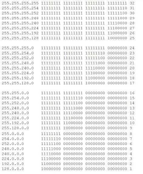
3.7CIDR
(Classless Inter-Domain Routing)
IP netmasks and CIDR are methods of notation
that combine several IP addresses to create a single address area. An
area comprising consecutive addresses is handled like a network.
To specify an area of IP addresses for the
mGuard, e.g., when configuring
the firewall, it may be necessary to specify the address area in CIDR
format. In the table below, the left-hand column shows the IP netmask,
while the right-hand column shows the corresponding CIDR format.
Example: 192.168.1.0/255.255.255.0 corresponds
to CIDR: 192.168.1.0/24
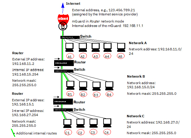
3.8Network example diagram
The following diagram shows how IP addresses
can be distributed in a local network with subnetworks, which network
addresses result from this, and how the details regarding additional internal
routes may look for the mGuard.
Table 3-2
Network example diagram
Network A |
Computer |
A1 |
A2 |
A3 |
A4 |
A5 |
IP address |
192.168.11.3 |
192.168.11.4 |
192.168.11.5 |
192.168.11.6 |
192.168.11.7 |
Network mask |
255.255.255.0 |
255.255.255.0 |
255.255.255.0 |
255.255.255.0 |
255.255.255.0 |
Network
B |
Computer |
B1 |
B2 |
B3 |
B4 |
Additional
internal routes
Network:
192.168.15.0/24
Gateway:
192.168.11.2
Network:
192.168.27.0/24
Gateway:
192.168.11.2 |
IP address |
192.168.15.2 |
192.168.15.3 |
192.168.15.4 |
192.168.15.5 |
Network mask |
255.255.255.0 |
255.255.255.0 |
255.255.255.0 |
255.255.255.0 |
Network
C |
Computer |
C |
C2 |
C3 |
C4 |
IP address |
192.168.27.1 |
192.168.27.2 |
192.168.27.3 |
192.168.27.4 |
Network mask |
255.255.255.0 |
255.255.255.0 |
255.255.255.0 |
255.255.255.0 |
3.9LED
status indicator and blinking behavior
With the help of built-in LED diodes, mGuard
devices indicate different system states. This can be status, alarm or
error messages.
Detailed information on the LEDs can be found
in the Appendix (see “LED status indicator and blinking behavior”
on page 365).