Firewall redundancy can currently only be enabled if no VPN connections are configured on the device.
|
Firewall redundancy can currently only be enabled if no VPN connections are configured on the device. |
|
The firewall redundancy functions are not available on the devices of the FL MGUARD 2000 series. |
|
Redundancy is described in detail in Section 13, “Redundancy”. |
|
To use the redundancy function, the same firmware must be installed on both mGuard devices. |
|
When the redundancy function is activated, VLAN cannot be used in Stealth mode. |
10.1Redundancy >> Firewall Redundancy
|
|
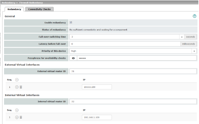
Deactivated (default): firewall redundancy is disabled. Activated: firewall redundancy is enabled.
|
|
|
General |
Status of redundancy |
Shows the current status. |
|
|
Maximum time that is allowed to elapse in the event of errors before switching to the other mGuard device . |
|
|
|
0 ... 10,000 milliseconds, default: 0 Time the redundancy system ignores an error. The connectivity and availability checks ignore an error unless it is still present after the time set here has elapsed. |
|
|
|
high/low Specifies the priority associated with the presence notifications (CARP). Set the priority to high on the mGuard device that you want to be active. The device on standby is set to low. Both devices in a redundancy pair may either be set to different priorities or to high priority. . 
|
|
|
|
On an mGuard device which is part of a redundancy pair, checks are constantly performed to determine whether an active mGuard is available and whether it should remain active. A variation of the CARP (Common Address Redundancy Protocol) is used here. CARP uses SHA-1 HMAC encryption together with a password. This password must be set so it is the same for both mGuard devices. It is used for encryption and is never transmitted in plain text. 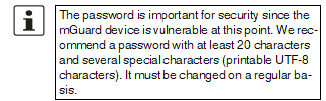
|
|
|
|
When changing the password, proceed as follows: Set the new password on both mGuard devices. It does not matter which order you do this in but the same password must be used in both cases. If you inadvertently enter an incorrect password, follow the instructions under “How to proceed in the event of an incorrect password” on page 286. As soon as a redundancy pair has been assigned a new password, it automatically negotiates when it can switch to the new password without interruption. |
|
|
|
If one device fails while the password is being changed, the following scenarios apply: –Password replacement has been started on all mGuard devices and then interrupted because of a network error, for example. This scenario is rectified automatically. –Password replacement has been started on all mGuard devices. However, one mGuard then fails and must be replaced. –Password replacement has been started but not performed on all mGuard devices because they have failed. Password replacement must be started as soon as a faulty mGuard is back online. If an mGuard device has been replaced, it must first be configured with the old password before it is connected. |
|
|
|
How to proceed in the event of an incorrect password 
If you can still remember the old password, proceed as follows: •Reconfigure the device on which the incorrect password was entered so that it uses the old password. •Wait until the device indicates that the old password is being used. •Then enter the correct password. If you have forgotten the old password, proceed as follows: •Check whether you can read the old password from the other device. •If the other deivce is disabled or missing, you can simply enter the correct new password on the active device on which you inadvertently set the incorrect password. Make sure that the other device is assigned the same password before operating it again. •If the other device is already using the new password, you must make sure that the device with the incorrect password is not active or able to be activated, e.g., by removing the cable at the LAN or WAN interface. In the case of remote access, you can enter a destination for the connectivity check that will not respond. Prior to provoking this type of error, check that there is no redundancy error on any of the mGuard devices. One device must be active and the other must be on standby. If necessary, rectify any errors displayed and only then use this method. After that, follow these steps: –Replace the incorrect password with a different one. –Enter this password on the active device too. –Restart the device that is not active. You can do this, for example, by reconnecting the Ethernet cable or restoring the old settings for the connectivity check. |
|
|
External Virtual Interfaces |
1, 2, 3, ... 255 (default: 51) Only in Router network mode. This ID is sent by the redundancy pair with each presence notification (CARP) via the external interface and is used to identify the redundancy pair. This ID must be the same for both mGuard devices. It is used to differentiate the redundancy pair from other redundancy pairs that are connected to the same Ethernet segment via their external interface. Please note that CARP uses the same protocol and port as VRRP (Virtual Router Redundancy Protocol). The ID set here must be different to the IDs on other devices which use VRRP or CARP and are located in the same Ethernet segment. |
|
|
|
Default: 10.0.0.100 Only in Router network mode. These are IP addresses which are shared by both mGuard devices as virtual IP addresses of the external interface. These IP addresses must be the same for both mGuard devices. These addresses are used as a gateway for explicit static routes for devices located in the same Ethernet segment as the external network interface of the mGuard device. The active mGuard device can receive ICMP requests via this IP address. It responds to these ICMP requests according to the menu settings under Network Security >> Packet Filter >> Advanced. No network masks or VLAN IDs are set up for the virtual IP addresses as these attributes are defined by the real external IP address. For each virtual IP address, a real IP address must be configured whose IP network accommodates the virtual address. The mGuard device transmits the network mask and VLAN setting from the real external IP address to the corresponding virtual IP address. The applied VLAN settings determine whether standard MTU settings or VLAN MTU settings are used for the virtual IP address. 
|
|
|
Internal Virtual Interfaces |
Internal virtual router ID |
1, 2, 3, ... 255 (default: 52) Only in Router network mode. This ID is sent by the redundancy pair with each presence notification (CARP) via the external and internal interface and is used to identify the redundancy pair. This ID must be set so it is the same for both mGuard devices. It is used to differentiate the redundancy pair from other Ethernet devices that are connected to the same Ethernet segment via their external/internal interface. Please note that CARP uses the same protocol and port as VRRP (Virtual Router Redundancy Protocol). The ID set here must be different to the IDs on other devices which use VRRP or CARP and are located in the same Ethernet segment. |
|
|
Internal virtual IP addresses (IP) |
As described under External virtual IP addresses (IP), but with two exceptions. Under Internal virtual IP addresses (IP), IP addresses are defined for devices which belong to the internal Ethernet segment. These devices must use the IP address as their default gateway. These addresses can be used as a DNS or NTP server when the mGuard device is configured as a server for the protocols. For each virtual IP address, a real IP address must be configured whose IP network accommodates the virtual address. The response to ICMP requests with internal virtual IP addresses is independent from the settings made under Network Security >> Packet Filter >> Advanced. |
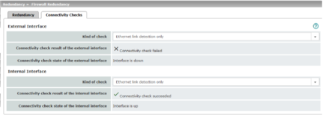
Targets can be configured for the internal and external interface in the connectivity check. It is important that these targets are actually connected to the specified interface. An ICMP echo reply cannot be received by an external interface when the corresponding target is connected to the internal interface (and vice versa). When the static routes are changed, the targets may easily not be checked properly.